background image

en


12   | ACX2281 |   Description of unit


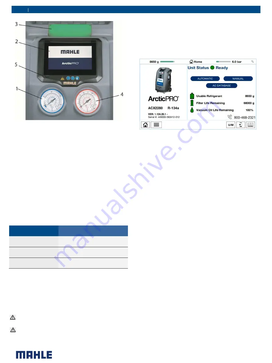
Fig. 5: Display and operating unit 

1. 

Low Side pressure gauge 

2. 

LCD Touch Screen 

3. 

Status and warning indicator light 

4. 

High Side pressure gauge 

5. 

USB port 


To select a function in the menu, press the text name of the function 
and the selection occurs when finger is released.  The selected entry 
is highlighted with a different color (from blue to gray) and the menu 
screen pages changes.


Fig. 6:   ACX2281 Home Screen 

If there are menus that cannot fit on one screen, there will be arrows 
located on a side of the screen. By placing finger on screen and 
swiping left/right, the screen options will also move.


The menu selection and necessary entries are made by way of the 
LCD touch screen (Fig. 5, Pos. 2) integrated in the panel. 

The pressure gauges (Fig. 5, Pos.1,4) of the display and operating unit 
are used to monitor the pressure during the individual vehicle A/C 
service phases. The status of the various service phases during 
maintenance is displayed on the LCD screen (Fig. 5, Pos. 2). 

The status and warning indicator light (Fig. 5 Pos. 3) indicates the 
service status.  See chart below for further definition. 

Status and warning light color 

Maintenance status 

Red Light 

Error/warning 

Flashing green 

Operation in progress 

Green light 

Operation complete/Attention Operator 

Input Selection 


5.1 

Selection and function key 

All settings, controls and service functions are available on the LCD 
touch display. Data entry and moving of the cursor is performed with 
user's finger or another object such as a pen or stylus. The LCD 
displays the service equipment's status, the progress of A/C system 
service and any alarms/error messages. 

Do not use a sharp, pointed object on the touch screen. 
Damage may occur! 
Although the LCD touch screen is glass, do not use harsh 
chemicals to clean the surface.  Standard glass cleaner is 
recommended  


Summary of Contents for ACX2281

Page 1: ...MAHLE ACX2281 EN Operation Manual A C Service Equipment...

Page 2: ...en 2 ACX2281...

Page 3: ...e of connection of external refrigerant bottle 17 7 5 Internal Bottle Fill 17 8 A C service preparation 18 8 1 Preliminary preparation 18 8 2 Non condensable gas discharge 18 8 3 Charge Modes 18 8 3 1...

Page 4: ...led and instructed personnel only Personnel scheduled to be trained familiarized and instructed or to take part in a general training course may only work with the product under the supervision of an...

Page 5: ...towards the prevention of accidents industrial diseases labor related health risks are taken and measures towards making the workplace fit for people to workinarecarriedout Basic rules The contractor...

Page 6: ...If the refrigerant has been contaminated by being mixed with other gases remove the contaminated refrigerant and add fresh R1234yf before using the ACX2281 for A C service R1234yf is not to be used in...

Page 7: ...r safety reasons it is advisable to use a residual current operated circuit breaker rccb with the following specifications Parameters Rated voltage 110 VAC 10 Rated frequency 50 60Hz Rated current 10A...

Page 8: ...antity 250ml Compressor capacity 0 87cu in 14cc Dryer filter 90kg recovered R1234yf Non condensable gas purge Automatic via solenoid valve HP and LP taps Automatic Display 7 inch capacitive touch scre...

Page 9: ...an only be operated with R1234yf The ACX2281is not to be used for service work on vehicles with air conditioning systems employing refrigerants other than R1234yf as this will cause damage Prior to A...

Page 10: ...er 5 Power Cord socket 4 Description of unit Fig 3 Front Left view 1 Vacuum pump oil level sight glass Fig 2 Rear View 1 Service Hoses 2 Fan 3 Vent 4 Hose Storage Fig 1 Front Right View 1 Rear Handle...

Page 11: ...Description of unit ACX2281 11 en Fig 4 Internal components 1 Accumulator Oil separator 2 Combo filter 3 Compressor 4 Vacuum pump 5 Refrigerant tank 6 HS compressor oil separator 7 Manifold...

Page 12: ...e used to monitor the pressure during the individual vehicle A C service phases The status of the various service phases during maintenance is displayed on the LCD screen Fig 5 Pos 2 The status and wa...

Page 13: ...the cylinder Avoid the refrigerant loss dispersion in the air during the disconnection of the couplers Puff effect CheckpossibleSchradervalveleaksbefore disconnection Fig 8 EcoLOCK Couplers To connect...

Page 14: ...to generate a vacuum in the air conditioning system which removes excess moisture and to detect possible leaks in the vehicle air conditioning system Used oil is separated from the recovered vehicle...

Page 15: ...erations described in this manual Remove staples and remove the carton Fig 10 Slowly lower the unit from pallet by means of the rear wheels Fig 12 Fig 12 Lowering unit from the pallet Keep the pallet...

Page 16: ...ations 7 2 First start up verification Warning Risk of frostbite from escaping refrigerant Refrigerant causes frostbite on the skin Check the service hoses for damage Firmly connect the service quick...

Page 17: ...stbite on the skin Check the service hoses for damage Firmly connect the service quick release couplings to the service hoses Wear protective goggles Wear protective gloves Before the ACX2281 can be u...

Page 18: ...stalled in vehicle A C system Lubricant removed from the system and or equipment shall be disposed of in accordance with the applicable federal state and local procedure and regulations The service pa...

Page 19: ...failed identifications 2 Switch off the ACX2281 unit 3 Disconnect power cord from outlet 4 Move unit outside 5 Connect High and Low side couplers to the Parking Flush adapter and open valves to equal...

Page 20: ...ess the green arrow in the lower right corner of the screen Fig 17 Automatic setting confirmation 6 If settings are correct press START button to begin process 9 3 Manual cycle setup Access to manual...

Page 21: ...n in Figure below will appear Fig 19 Vacuum time adjustment 4 Swipe finger up or down to adjust the hours and minutes then press the to accept or the X to cancel time adjustment 5 If the vacuum test t...

Page 22: ...e menu prompting to complete oil flushing 9 8 Vehicle Pressure Check 1 From the MENU scroll to SPECIAL FUNCTIONS and select The SPECIAL FUNCTIONS screen will now be displayed Fig 23 Vehicle pressure c...

Page 23: ...tion fittings To ensure a reliable procedure it is advisable to use the optimum quantity of refrigerant The optimum quantity of refrigerant for the ACX2281is 4kg 10 0kg An inadequate quantity of refri...

Page 24: ...and the filter dryer need replacement 1 From the MAINTENANCE menu scroll until MAINTENANCE COUNTERS is shown and make selection 2 Press to display all counters Fig 28 Maintenance counters 10 6 Long li...

Page 25: ...ervice life Each filter is marked with a unique code This code must be entered when replacing the filter It is not possible to operate the ACX2281 if the same code is re used It is advisable to keep a...

Page 26: ...locking screw and lift the front housing 7 Once the unit is open inspect the clear hose coming from the back of the identifier down to the manifold assembly 8 Replace sample clear hose if oil is pres...

Page 27: ...acuum pump oil 011 80070 00 Paper for printer 5 rolls 360 83110 00 Service hose HP 360 82948 00 Service hose LP 360 82949 00 Quick release coupling HP 360 82950 00 Quick release coupling LP 360 82951...

Page 28: ...Maintenance ACX2281 28 en 12Maintenance 12 1 Vacuum pump oil change Vacuum pump oil change record Date Maintenance technician identification Maintenance technician signature and stamp...

Page 29: ...en 29 ACX2281 Maintenance Vacuum pump oil change record Date Maintenance technician identification Maintenance technician signature and stamp...

Page 30: ...Maintenance ACX2281 30 en 12 2 Filter dryer change Filter Dryer Change Record Date Maintenance technician identification Maint Tech signature and stamp...

Page 31: ...en 31 ACX2281 Maintenance Filter Dryer Change Record Date Maintenance technician identification Maint Tech signature and stamp...

Page 32: ...Maintenance ACX2281 32 en Filter Dryer Change Record Date Maintenance technician identification Maint Tech signature and stamp...

Page 33: ...aintenance 12 3 Refrigerant load cell calibration check Refrigerant Load Cell Calibration Check Record Date Result of check pass fail Maintenance technician identification Maintenance technician signa...

Page 34: ...nance ACX2281 34 en 12 4 Other checks maintenance repairs Other checks maintenance repairs Job Date Result of check pass fail Maintenance technician identification Maintenance Technician signature and...

Page 35: ...en 35 ACX2281 Maintenance 12 5 Notes...

Page 36: ...MAHLE Aftermarket Inc Service Solutions 23030 MAHLE Drive Farmington Hills MI 48335 USA 717 840 0678 www servicesolutions mahle com 035 82693 01 REV A 2021 10 18...

Reviews: