43
Maxuum III Digital Electronic Indicator 2239028 Rev D
8.0 Output Information
The Maxum III comes complete with digital output for commu-
nication with data collection devices. Three outputs are avail-
able on the Maxum III Indicator. The output to be used by the
operator is selectable in one of three formats:
• Standard Maxum
• Serial ASCII
• Digimatic or BCD
The output from the indicator is based on the selection that is
set in the Setup Mode. The output port may also be turned Off
as part of the setup selection. The default setting is for Standard
(St) Maxum format. To change to the other optional formats
(see Section, ’3.0 Setup Mode’ on page 14).
CAUTION: Make sure proper cable and device connections are
used with the data output selected on the indicator. improper
use and lack of compatibility could be cause for system com-
ponent malfunction.
A plastic cap covers the output receptacle when not in use. The
pin-outs and description for each output format is described as
follows:
8.1 STD Maxum Output
This format, consisting of a clock signal, 35 bit data stream and
a plus/minus signal, has allowed for communication to virtually
all data collection devices. Because of the remote HOLD and
RESET features we offer two connector configurations. These
are specified as 6-pin or 10-pin as part of the Maxum III order-
ing number.
The standard Maxum output is provided through a six pin con-
nector. (Since this is the old format, most existing data collection
devices will be compatible with this connector.)
The 10-pin is the same output format which includes control
lines for HOLD and RESET.
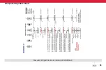
Maxum III models using the 6-pin or 10-pin connector and out-
put format selected for Standard Maxum have a pin-out desig-
nation as follows:


