47
Maxuum III Digital Electronic Indicator 2239028 Rev D
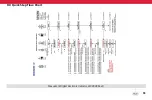
The Maxum III serial output bits 23, 24, and 25 marked with an
‘X’ is not used. However, for Maxum III Enhanced Mode use the
table on page 46.
NOTES:
• P1, P2, P3 - Refers to period digit number. i.e., P2 period on
digit 2
• BIT 1 through BIT 21 - Refers to segment location digit
numbers. i.e., - c3; segment c of digit 3
• A2 - Segments a, d, e and f of digit 2 are on or off.
• B2 - segments b and c of digit 2 are on or off.
• BIT 28 - Logic Low (0) units are in inch. Logic high (1) ‘mm’
units in millimeters.
• BIT 30 - Low battery warning bit set during low battery
warning condition.
• BIT 35 - Logic Low (0) polarity of reading is a positive value.
Logic high (1), ‘-’ polarity of reading is a negative value.
8.1.5 Signal Input
8.1.5.1 HOLD/UPDATE
In the Enhanced Mode, this control performs a toggle function
to either HOLD or UPDATE the Maxum III dynamic measure-
ments. In this manner, the unit can be made to freeze the last
set of readings:
• Actual
• MAX
• MIN
• TIR
After UPDATE has been activated, the display will resume oper-
ations, and the Actual, MAX, MIN, and TIR values are updated
as if there had been no interruption. The assertion signal is a
momentary logic 110, (GND) of at least 100
μ
Sec. duration.
In the Standard Mode, connecting this input to GND causes the
unit to enter the True Spindle Mode of control. This only occurs
when the unit has an on-scale reading.
8.1.5.2 RESET/ZERO (Wake-Up)
This input performs the WAKE-UP function from a ‘Sleep’ mode
condition.
In the Enhanced Mode, this input resets the dynamic measure-
ment reading. The currently displayed value becomes the maxi-
mum and minimum values, and the TIR value becomes zero. If
the unit is in the Actual mode of operations, this input performs
the ZERO function as described in the reference note below.


