background image

uk 

│ 9. Installation ‒ Electrical connection 


18 

4.  Fix the fan into position at the installation 

location using fixing material that is 
approved for the corresponding load. 


Use spring washers or lock nuts to 
ensure long-term fixing. Take note of 
the torque values quoted by the dowel 
manufacturer. Build in the steel wall 
ring without distorting it by twisting or 
squeezing it. The impeller must not rub. 

5.  Check both the free running of the impeller 

and the air gap between the impeller and 
the steel wall ring, by turning the impeller 
by hand.  


The impeller must not rub and the air 
gap must be more or less the same 
all the way round. 

6.  Install a shutter or a protective grille on the 

outside, in order to safeguard the fan 
against foreign bodies falling into the air 
channel. Insure there is protection against 
accidental contact, in accordance with EN 
ISO 13857. 


Always use new lock nuts in 
accordance with EN ISO 7041, when 
assembling and dismantling. 


9.2 Electrical connection 


DANGER 

Danger to life from electric 
shock. 

Prior to accessing the connection 
terminals, switch off all supply 
circuits. Switch off mains fuse, 
secure against being accidentally 
switched back on and position a 
visible warning sign. 


NOTICE


Risk of damage to unit in the 
event of short-circuits. 

Insulate any unnecessary cable 
cores. 


Information


●  Always note the relevant specifications for 

electrical installations and when fitting 
equipment. In Germany observe DIN VDE 
0100 and the corresponding parts in 
particular. 

●  Connect the fan to a current-dependent 

protection device. This should be supplied 
by the customer 

 see protection device 

operating instructions for relevant data. 


Procedure 

1.  Switch off mains fuse and prevent from 

being started up again. Fit warning sign. 

2.  Remove the terminal box cover [3]. 


NOTICE 

Danger of short circuits and 
damage to unit. Water may 
penetrate the terminal box if 
the power cable is introduced 
incorrectly or if sealing 
elements such as a self-
sealing grommet, cable 
grommet or cable screw-
connections are not fitted 
correctly. 

Install the sealing elements 
such that the power cable is 
held snugly in place.


3.  Install suitable sealing element such as a 

self-sealing grommet, cable grommet or 
cable screw-connections. 

4.  Guide the power cable into the terminal 

box such that the sealing element fits 
around the cable sheathing completely.  
If necessary, seal the terminal box on-site. 

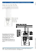
5.  Wire fan to the terminal block according to 

the wiring diagram (

 Chapter 17). Note 

tightening torque of screws of 0.7 Nm. 


NOTICE 

Risk of damage to unit if 
unauthorised external control 
device is used. 

Only connect control devices 
with a current-dependent 
protection device.


6.  Wire external control device to the terminal 

block according to the wiring diagram  
(

 Chapter 17). Note tightening torque  

of screws of 0.7 Nm. 


Summary of Contents for DAS 71/4

Page 1: ...al wall fans Ventilateurs mureaux h lico des DAS 71 DAS 80 DAS 100 DAS 112 DAS 125 Montage und Betriebsanleitung Mounting and Operating instructions Instructions de montage et Mode d emploi www m aico...

Page 2: ...t unter maico ventilatoren com DAS 71 DAS 125 1 Lieferumfang DAS Wandventilator mit Stahlwandring Montage und Betriebsanleitung 2 Allgemeine Hinweise Lesen Sie diese Montage und Betriebsanleitung vor...

Page 3: ...oder seiner Umgebung f hren k nnte INFO Symbol f r wichtige Infor mationen und Tipps Aufz hlungssymbol f r Informa tionen zum jeweiligen Thema 1 Handlungsanweisung F hren Sie die angegebenen Anwei sun...

Page 4: ...latoren dienen zur Entl ftung von Produktionsst tten Montagehallen Lager r umen Gewerber umen Garagen Ausstellungsr umen Fabrikationsst tten Industriehallen Kompressor Trafor umen oder sonstigen Gewer...

Page 5: ...dem Typenschild angegebene Schutzart ist nur gew hrleistet bei bestim mungsgem em Einbau und bei ordnungsgem er Einf hrung der Leitungen in den Anschlusskasten Ger t nur an einer fest verleg ten elekt...

Page 6: ...Gefahren verstehen Kinder d rfen nicht mit dem Ger t spielen Reinigung und Be nutzer Wartung d rfen nicht von Kindern ohne Beaufsichti gung durchgef hrt werden 7 Transport Lagerung 7 1 Transport GEFAH...

Page 7: ...ein Schutzgitter montieren 4 F r ausreichende Zuluft Nachstr mung sorgen 9 Montage 9 1 Ventilatormontage GEFAHR Gefahr bei falschem Montage ort oder falscher Befestigung 1 Ger t nur an Orten mit ausre...

Page 8: ...se Bei Elektroinstallation und Ger temontage unbedingt die einschl gigen Vorschriften beachten in Deutschland insbesondere DIN VDE 0100 mit den entsprechenden Teilen Ventilator an eine stromabh ngige...

Page 9: ...den 9 4 Inbetriebnahme 1 S mtliche Schraubenverbindungen auf festen Sitz pr fen 2 Luftkanal auf Verschmutzungen pr fen und falls erforderlich reinigen 3 Anschlussdaten mit den technische Daten des Ger...

Page 10: ...ten im Bereich des Motors das Ger t ausreichend abk hlen lassen Erst dann Schutzgitter 2 entfernen St rung Ursache Ma nahme Ventilator schaltet nicht ein Keine Netzspannung Pr fen ob die Netzsiche run...

Page 11: ...montage darf nur von einer Elektrofachkraft Kapitel 2 vorgenommen werden GEFAHR Lebensgefahr durch Strom schlag Vor Zugang zu den Anschluss klemmen alle Versorgungsstrom kreise abschalten Netzsicherun...

Page 12: ...before using the fan for the first time Follow the instructions Keep these instructions safe for use later on 2 1 Installation staff Installation may only be carried out by specialists who have the ne...

Page 13: ...ions given in the order stated 3 Product information 3 1 Equipment overview Fig A 1 Steel wall ring 2 Protective grille varnished 3 Terminal box cover 4 Terminal box 5 Motor 6 Impeller 7 Motor stand w...

Page 14: ...ns are used for the ventilation of production areas assembly halls warehouses commercial premises garages showrooms production sites industrial buildings compressor transformer rooms or other commerci...

Page 15: ...of protection stated on the rating plate is only guaranteed if installation is undertaken correctly and if the cables are correctly guided into the terminal box Only connect unit to perma nently wired...

Page 16: ...rstand the resulting risks thereof Children must not play with the unit Cleaning and maintenance must not be carried out by children without supervision 7 Transportation storage 7 1 Transport DANGER D...

Page 17: ...f a free air entry or exit 4 Ensure a sufficient fresh air supply intake 9 Installation 9 1 Fan installation DANGER Danger from incorrect installation location or incorrect attachment 1 Only fit in pl...

Page 18: ...cores Information Always note the relevant specifications for electrical installations and when fitting equipment In Germany observe DIN VDE 0100 and the corresponding parts in particular Connect the...

Page 19: ...frequency converter 9 4 Commissioning 1 Check that all screw connections are tight 2 Check air channel for dirt and clean if necessary 3 Check that connection data matches technical data on the unit u...

Page 20: ...d motor in the case of a fault Let the device cool down sufficiently before working in the area of the motor Only then remove the protective grille 2 Fault Cause measure Fan does not switch on No main...

Page 21: ...ntling may only be under taken by a trained electrician Chapter 2 DANGER Danger to life from electric shock Prior to accessing the connection terminals switch off all supply circuits Switch off mains...

Page 22: ...montage avant la premi re utilisation du ventilateur Respectez les instructions Conservez ces instructions pour une utilisation ult rieure Installateurs Seul un personnel agr et disposant de connaissa...

Page 23: ...e X Al sage 16 ou 20 pi ces en fonction du type d appareil 3 2 Direction de refoulement Fig B Sens de refoulement par aspiration au travers du moteur Sens de rotation de l h lice 3 3 Description du pr...

Page 24: ...u sur des supports avec portances suffisantes avec un pied de moteur situ sur la face inf rieure et une position d installation horizontale sens du flux selon la fig B lorsque l appareil est enti reme...

Page 25: ...x directives et de l insertion correcte des c bles dans les borniers Brancher exclusivement l appareil sur une installation lectrique permanente avec des c bles de type NYM O ou NYM J 5 x 1 5 4 mm en...

Page 26: ...c l appareil Les enfants sans surveillance ne doivent pas nettoyer l appareil ou proc der des travaux d entretien revenant l utilisateur 7 Transport Stockage 7 1 Transport DANGER Risque de blessure l...

Page 27: ...ble secteur sur le lieu d installation 3 Si l entr e et la sortie d air sont libres monter une grille de protection devant l appareil 4 Veiller ce que le flux d air amen est suffisant 9 Montage 9 1 M...

Page 28: ...cordement couper tous les circuits d alimentation lectrique D sactiver le fusible secteur s curiser contre toute remise en service intempestive et apposer un panneau d avertissement de mani re bien vi...

Page 29: ...MFU fournir par le client mode d emploi du convertisseur de fr quence Dans ce cas l la protection moteur est assur e par le convertisseur de fr quence La fr quence de sortie du convertisseur ne doit p...

Page 30: ...sulter un lectricien qualifi Les r parations sont exclusivement r serv es des lectriciens qualifi s DANGER P ril de mort par lectrocution Avant d acc der aux bornes de raccordement couper tous les cir...

Page 31: ...abat du mode d emploi 3 Num ro de la position Adressez vos questions Maico Elektroapparate Fabrik GmbH Steinbeisstra e 20 78056 Villingen Schwenningen Allemagne T l 49 7720 694 445 Fax 49 7720 694 175...

Page 32: ...ctor Remove bridges V2 U2 W2 on the terminal strip of the DAS En cas d utilisation d un interrupteur en triangle Enlever les ponts V2 U2 W2 qui se trouvent sur les barrettes deraccor dement Maico Elek...

Reviews: