10
4. Product information
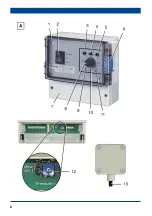
Operating modes with switch [2]
● Automatic operation (=temperature-
controlled operation): Room temperature is
changed by the supply of outside air with
fan until the setpoint temperature selected
with rotary knob [8] is reached, see
“Temperature control”.
Green indicator light [11] lights up.
● Off: Fan switches off, green indicator light
[11] is off.
● Continuous operation: Fan runs at set
minimum speed.
Green indicator light [11] lights up.
Temperature control
● When the unit is switched on with switch
[2], the fan starts up at maximum speed.
The speed is then reduced in proportion to
the change in temperature on the
temperature sensor [13].
● If the room temperature is above the
setpoint temperature, the fan speed
increases to the maximum value set with
potentiometer [5].
● The fan speed decreases as the room
temperature falls through the supply of cold
outside air, for example. At setpoint
temperature, the minimum value set with
potentiometer [3] is reached.
● “XP” speed range: Potentiometer [4] is
used to define how quickly the maximum
fan speed is to be reached. Fan runs at
maximum speed for “setpoint temperature
+ adjustable value”. For example, when
“XP = 5”, the maximum fan speed is
reached at a room temperature 5 K above
the setpoint temperature.
● If the room temperature falls at least 3 °C
below the setpoint temperature, the fan
speed is either
– controlled using limit value switch-off.
The fan switches off automatically until
setpoint temperature is reached again.
– or the fan runs constantly at minimum
speed. Setting is made using jumper [12].
Ex factory = limit value switch-off “On”.
Dimensions
● EAT 6 G/1 unit (W x H x D):
188 x 159 x 110 mm
● Temperature sensor (W x H x D):
8.7 x 13 x 4.5 mm
Power supply
● Rated voltage: 230 V
● Nominal current range: 0.2 A eff. to 6 A, eff.
● Power frequency: 50 Hz
Protection class
● Degree of protection: IP 54 (splash water
protected)
5. Environmental conditions and
operating limits
● Maximum permitted temperature of the air
medium: +40 °C
6. Technical data
● Refer to the rating plate and/or valid
catalogue.
7. Installation
Select installation location for EAT 6 G/1
unit [1] and make sure there is a flat
surface.
Select installation location for temperature
sensor [13]:
– High up in the room.
– Not in a corner.
– Temperature sensor may only be
installed pointed downwards.
Lay cables, for permitted types see chap. 4:
– Use 2-core control cable between EAT 6
G/1 unit and temperature sensor and
– use 3-core control between EAT 6 G/1
unit and fan.
Lay power cable.
Fit central screw for EAT 6 G/1 unit. For
spacing, refer to rear of unit. Suitable
mounting material is to be provided by the
customer.


