11
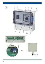
Remove terminal box cover [7] from EAT 6
G/1 unit [1].
Cut through desired cable lead-throughs at
knockout points on underside of EAT 6 G/1
housing.
CAUTION
Unit will be damaged by water
ingress or moisture.
Only lead cables into EAT 6
G/1 housing from underneath.
If this is not done, the degree
of protection cannot be
guaranteed.
Hang EAT 6 G/1 unit on central screw and
secure in the bottom right and left with
2 locking bolts. Suitable mounting material
is to be provided by the customer.
Guide all connecting cables into the
housing.
Remove cover from temperature sensor
[13].
Cut through desired cable lead-through at
one knockout point on side
of temperature sensor housing.
Fit cable grommet on housing.
Fit temperature sensor housing on wall. For
spacing, refer to rear of housing. Suitable
mounting material is to be provided by the
customer.
Feed cable into the housing.
8. Electrical connection
CAUTION
Risk of damage to unit in the
event of short-circuits!
Cut off and insulate cable
cores that are not required.
Information
● EAT 6 G/1 unit is fitted with a 0...10 V
output for optional EALT 6 power unit
(for permitted maximum loading = 12 A).
● The output voltage at EALT 6 (+/- terminal)
is proportional to the controlled 0...10 V
voltage.
Connecting temperature controller
Strip cables.
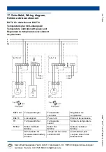
Connect power cable and control cables as
shown in wiring diagram on page 7.
Fit cover on temperature sensor [13].
Ensure that the sealing in the cover is
inserted correctly and is sealed all the way
around.
Check position of jumper [12] in EAT 6 G/1
terminal box and move if desired:
Limit value switch, On.
Fan switches off when temperature
falls below setpoint temperature by
at least 3 °C and switches back on
when setpoint temperature is
exceeded.
Limit value switch, Off.
Fan runs at minimum speed when
temperature falls below setpoint
temperature by at least 3 °C.
Fit terminal box cover [7] on EAT 6 G/1
unit [1].
Switch the mains fuse on.
Run function test.
9. Commissioning – temperature-
controlled operation
Move operating mode switch [2] into
“Automatic” position.
● Unit switches on.
Use potentiometer [5] to set “XP” speed
range:
– All the way to the left, approx. 2 K
– All the way to the right, approx. 10 K
Use rotary knob [7] to select setpoint
temperature. Setting range 5...35 °C.
Use potentiometer [6] to select maximum
fan speed.
Use potentiometer [4] to select minimum
fan speed.
i


