gb │ 2. Product information
10
2. Product information
2.1 Unit overview, Fig. A, B and C
1
Spring hook
2
Cable grommet, rear
3
Cable grommet, top
4
Housing with motor
5
Electronic circuit board
5.1 Mother board (Standard, P, 24-V)
5.2 VZ circuit board
5.3 F circuit board
6
Terminal block
7
Electronics cover (VZ, KVZ, F, KF)
8
Motor protection cover
9
Impeller
10 ECA 120 K: Thermostatic bimetal strip
11 ECA 120 K: Bimetal cover
12 Internal grille / shutter frame
S Screw (not included in scope of delivery)
2.2 Product description
● ECA 120 with fixed internal grille.
● ECA 120 with electrically operated shutter
frame.
2.2.1 Models
●
Standard model:
Can be operated with
switch which is to be provided by the
customer. Unit, speed controllable.
● Model VZ with time delay switch. Can be
operated with switch which is to be
provided by the customer. Adjustable start
delay approx. 50 seconds and overrun
time approx. 6 minutes. Unit, not speed
controllable.
● Model F with light control, adjustable start
delay approx. 50 seconds and overrun
time approx. 6 minutes. Barrier-free
application. The light control switches the
fan automatically on and off: Switch-on
intensity at fan min. 30 lx, switch-off
intensity at fan max. 0.3 lx. Unit, not
speed controllable.
F units can be operated indepen-
dently of the lighting using the
optional light switch. The automatic
operating mode commences when
"Light on". If the light is switched off,
the unit continues to run until the
remaining overrun time has passed.
●
Model P:
With pull-cord switch.
Unit, not speed controllable.
● 24 V model with safety extra-low voltage
24 V, 50 Hz. Can be operated with
optional switch. Can be combined with
time delay switch VZ 6, VZ 12 or VZ 24 C
(see accessories). Unit, not speed
controllable.
2.3 Intended use
● ECA 120 and ECA 120 K are small room
fans for extracting air from rooms.
● These fan units are only intended for
domestic use and similar purposes.
● The fan units are used to extract air from
bathrooms, WCs, storage rooms, cellars,
single family-unit houses, offices and
similar places.
● Operation is only permitted when:
● fixed installation within buildings.
● surface installation on walls, ceilings
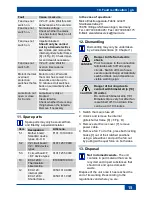
or ducts.
● air supply via shaft or duct.
● permanent electrical connection,
surface-mounted or recessed-mounted.
● with sufficient space from the wall or
ceiling as shown in Fig. A.
● unit is completely installed.
● The operation of the 24 V model is only
permitted with approved safety isolating
transformer TRE 50 (230 V/24 V). The
time delay switches are to be installed
between switch (230 V) and input side of
the safety isolating transformer in
accordance with the wiring diagram.
Summary of Contents for ECA 120 SERIES
Page 3: ...A B C D...


