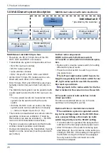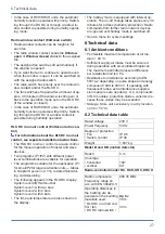
7 Preparation for installation
28
fan
• Fan / fan
• Amplifier / fan
30 m
40 m
For more technical data → rating plate.
For characteristic curves →
7 Preparation for installation
7.1 Wall
Use mounting material suitable for base and of
sufficient dimensions. Ensure sufficient supply air.
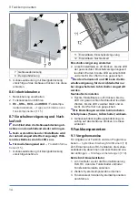
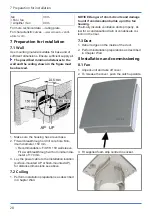
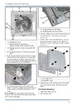
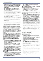
The prescribed minimum distances to the
wall and the ceiling shown in the figure must
be observed.
1. Make sure the housing has a level base.
2. Fit wall breakthrough or drill core hole: Min-
imum diameter, 150 mm.
ð
Recommendation: Fit WH 150 wall sleeve.
Fit a wall breakthrough with a minimum dia-
meter of 170 mm.
3. Lay the power cable to the installation location
(surface-mounted AP or flush-mounted UP),
for distance dimensions see above.
7.2 Ceiling
1. Perform installation preparations as described
in Chapter Wall.
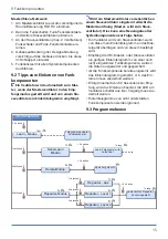
NOTICE Danger of short-circuits and damage
to unit if condensation builds up in the fan
housing.
Thermally insulate ventilation ducts properly. Al-
low for a condensation drain or condensate col-
lector in the riser.
7.3 Duct
1. Deburr edges on the inside of the duct.
2. Perform installation preparations as described
in Chapter Wall.
8 Installation and commissioning
8.1 Fan
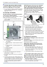
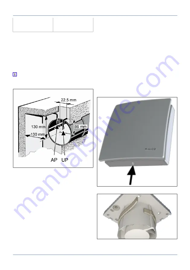
1. Unpack unit and take off cover.
2. To release the cover, push the catch upwards.
3. Fit supplied foam strip centred in socket.

