
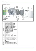
7 Montagevorbereitungen
10
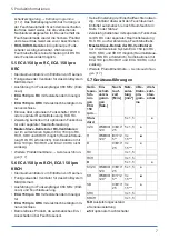
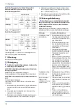
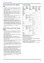
Funkausführung RC, RCH, KRC, KRCH
Funk-Komponenten:
Frequenzbereich (nach
EN 300220-1)
868,35 MHz
Reichweiten im Gebäu-
de, je nach Bausub-
stanz:
• Raumluftsteuerung
RLS RC / Ventilator
• Funkschalter DS RC /
Ventilator
• Ventilator / Ventilator
• Signalverstärker /
Ventilator
Bis zu:
30 m
30 m
30 m
40 m
Für weitere technische Daten → Typenschild.
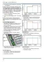
Für Kennlinien →
7 Montagevorbereitungen
7.1 Wand
Zum Untergrund passendes, ausreichend dimen-
sioniertes Befestigungsmaterial verwenden. Für
ausreichend Zuluft sorgen.
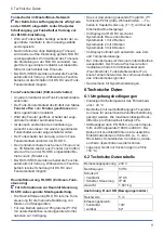
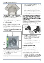
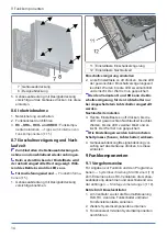
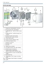
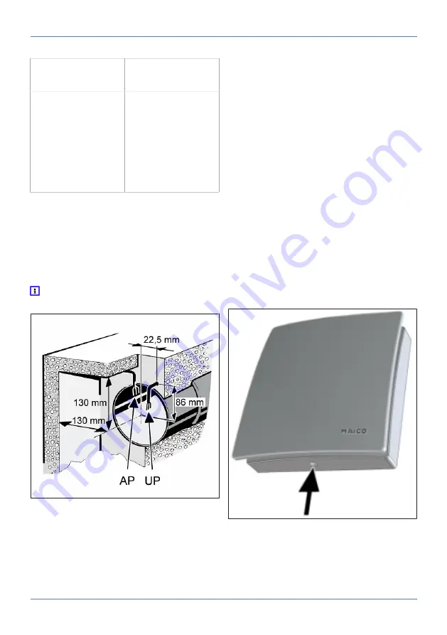
Vorgeschriebene Mindestabstände zur
Wand und Decke gemäß Abbildung einhalten.
1. Im Bereich des Gehäuses für einen ebenen
Untergrund sorgen.
2. Wanddurchbruch anbringen oder Kernloch
bohren: Mindestdurchmesser 150 mm.
ð
Empfehlung: Wandhülse WH 150 einbauen.
Einen Wanddurchbruch mit Mindestdurch-
messer 170 mm anbringen.
3. Netzleitung bis an den Montageort verlegen
(Aufputz AP oder Unterputz UP), für Ab-
standsmaße siehe oben.
7.2 Decke
1. Montagevorbereitungen wie in Kapitel Wand
beschrieben vornehmen.
ACHTUNG Kurzschlussgefahr und Gerätebe-
schädigung durch Kondenswasserbildung im
Ventilatorgehäuse.
Lüftungsleitungen fachgerecht thermisch isolie-
ren. Kondenswasserableitung oder Kondensat-
sammler in der Steigleitung einplanen.
7.3 Rohr
1. Kanten der Rohrinnenseite entgraten.
2. Montagevorbereitungen wie in Kapitel Wand
beschrieben vornehmen.
8 Montage und Inbetriebnahme
8.1 Ventilator
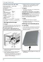
1. Gerät auspacken und Abdeckung abnehmen.
2. Zum Lösen der Abdeckung den Schnapper
nach oben drücken.
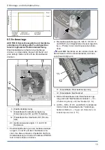
3. Beigefügtes Schaumstoffband am Stutzen mit-
tig anbringen.


