background image

5 Product information

24

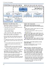
5.2 ECA 150 ipro VZC, ECA 150 ipro
KVZC

• Small room fans for extracting air from rooms.

• Model with adjustable start delay and overrun

time.

ECA 150 ipro VZC

 with fixed internal grille.

ECA 150 ipro KVZC

 with electrically operated

internal shutter.

• Two power levels as standard. Operation in

either level 1 or level 2.

• On/off with light switch or separate switch.

• Further product features → 

Unit versions

[

}

 25]

.

5.3 ECA 150 ipro B, ECA 150 ipro KB

• Small room fans for extracting air from rooms.

• Model with motion detector and overrun time.

No start delay.

ECA 150 ipro B

 with fixed internal grille.

ECA 150 ipro KB

 with electrically operated in-

ternal shutter.

• Barrier-free product as the fan switches itself on

and off via the motion sensor.

• Motion sensor range 5 m, horizontal monitoring

range 100°, vertical monitoring range 82°.

• Two power levels as standard. Operation in

either level 1 or level 2.

• Operation possible without switch. Can option-

ally also be switched via separate switch.

• Further product features → 

Unit versions

[

}

 25]

.

5.4 ECA 150 ipro H, ECA 150 ipro KH

• Small room fans for extracting air from rooms.

• Model with humidity control (fully automatic),

start delay and overrun time.

ECA 150 ipro H

 with fixed internal grille.

ECA 150 ipro KH

 with electrically operated in-

ternal shutter.

• Barrier-free product as the fan switches itself on

and off via the humidity sensor.

• Switch-on humidity does not have to be set.

Fan monitors the room humidity.

• 2 performance levels as a standard feature.

Fan extracts air automatically in level 1 or level
2, depending on the room humidity.

• Operation possible without switch. Can option-

ally also be switched via separate switch.

• Further product features → 

Unit versions

[

}

 25]

.

Automatic humidity function

Once the fan is installed, it adjusts to the room
humidity prevailing at that time (relative humidity).
This humidity value is saved as the first reference
value. The reference value does not have to be
specified manually.
If the relative humidity falls below the reference
value during operation, the newly established ref-
erence value is saved. The lowest possible refer-
ence value is 48 % relative humidity.

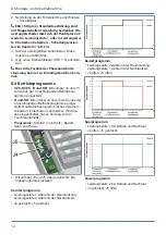
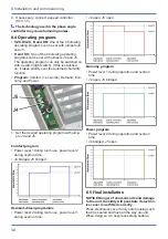
When the room humidity increases

• If the room humidity increases by 7%, the fan

switches on automatically at power level 1 (200
m³/h).

• If the humidity increases even further, the unit

switches to power level 2 (250 m³/h).

• If there are no further increases, the fan contin-

ues to run at power level 1 (200 m³/h) until the
humidity again falls below the saved reference
value.

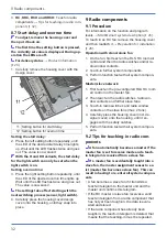
When falling below the reference value

H and KH:

 Overrun operation starts with the set

overrun time. The current reference value is
then saved.

RCH and KRCH:

 No overrun operation.

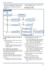
Value does not fall below reference value for 1
hour

H and KH:

 Overrun operation starts. Fan then

switches off.

RCH and KRCH:

 Fan switches off.

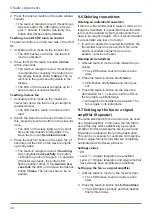
Operation using light and/or radio switch

H and KH units

 can also be operated using the

light switch. With “Light on”, the set operating
programme starts with the start delay → 

Oper-

ating programs [

}

 30]

 The operating program

takes priority over the automatic humidity func-
tion. After switching off, the unit continues to
run until the remaining overrun time has
passed. The automatic humidity function is then
assigned maximum priority again and controls
the unit as described above.

• Optionally, 

RCH/KRCH units

 can be operated

in 2 levels using a radio switch. Switching
through the DS RC or window contact is pos-
sible during humidity operating mode.

Summary of Contents for ECA 150 ipro

Page 1: ...d emploi Kleinraumventilatoren Small room fans A rateurs pour petites pi ces ECA 150 ipro ECA 150 ipro VZC ECA 150 ipro H ECA 150 ipro B ECA 150 ipro RC ECA 150 ipro RCH ECA 150 ipro K ECA 150 ipro KV...

Page 2: ...ehendes Innengitter 6 2 Elektrischer Innenverschluss K Ger te 6 3 Thermo Bimetall K Ger te 7 Abdeckung 7 1 oder 7 2 8 Designabdeckung 9 Sensoren 9 1 Bewegungssensor B KB 9 2 Feuchtesensor H KH RCH KRC...

Page 3: ...hnische Daten 9 6 1 Umgebungsbedingungen 9 6 2 Technische Datentabelle 9 7 Montagevorbereitungen 10 7 1 Wand 10 7 2 Decke 10 7 3 Rohr 10 8 Montage und Inbetriebnahme 10 8 1 Ventilator 10 8 2 Geh useei...

Page 4: ...se 4 1 Allgemeine Sicherheitshinweise Das Ger t darf in folgenden Situationen auf kei nen Fall eingesetzt werden GEFAHR Entz ndungs Brandgefahr durch brennbare Materialien Fl ssigkeiten oder Gase in d...

Page 5: ...tte unbedingt f r eine ausreichende Zuluftnachstr mung sorgen GEFAHR Gefahr durch Stromschlag bei Betrieb mit nicht komplett montiertem oder besch digtem Ventilator Vor dem Abnehmen des Elektronikabde...

Page 6: ...gitter ECA 150 ipro KH mit elektrisch bet tigtem In nenverschluss Barrierefreies Produkt da automatisches Ein Ausschalten ber Feuchtesensor Keine Einstellung der Einschaltfeuchte notwen dig Ventilator...

Page 7: ...RCH ECA 150 ipro KRCH Kleinraumventilator zum Entl ften von R umen Funkgesteuerter Ventilator f r das Abluftsystem MAICOsmart Ausf hrung mit Funkempf nger 868 MHz EnO cean und Feuchtesteuerung ECA 15...

Page 8: ...LS RC bedienen Mit einem Funkschalter lassen sich 2 Leis tungsstufen anw hlen oder das System aus schalten Mit der Raumluftsteuerung RLS RC lassen sich 3 Systemstufen manuell einschalten Tabelle im Ka...

Page 9: ...ean Funk steuerung F r Informationen zur Raumluftsteuerung RLS RC siehe separate Montageanleitung Die Raumluftsteuerung RLS RC ist eine Funk steuerung f r die manuelle Bedienung von Master und Slavege...

Page 10: ...chbruch anbringen oder Kernloch bohren Mindestdurchmesser 150 mm Empfehlung Wandh lse WH 150 einbauen Einen Wanddurchbruch mit Mindestdurch messer 170 mm anbringen 3 Netzleitung bis an den Montageort...

Page 11: ...dem Geh use neh men ACHTUNG Kurzschlussgefahr Ger tebesch digung Eindringendes Wasser bei falscher Einf hrung der Netzleitung in das Ventilator geh use oder bei nicht fachgerecht eingebau ten Leitung...

Page 12: ...rd eines der 4 nachfolgenden Betriebspro gramme eingestellt H und KH Mit Jumper J4 und J5 wird eines der 4 nachfolgenden Betriebsprogramme einge stellt Das Betriebsprogramm ist nur mit einem Schalter...

Page 13: ...usspa rungen I II und III auf die 3 Rastnasen ste cken bis diese einrasten Zus tzlich die Elek tronikabdeckung an beiden Positionen PRESS fest in das Geh use dr cken 2 Bei Ger teausf hrungen B KB H KH...

Page 14: ...leuchtet Warten bis die LED zweimal blinkt und erlischt Der Wert ist nun gespeichert Bei den Varianten H und KH kann die Ein schaltverz gerung f r den Lichtschalter nur bei eingeschaltetem Lichtschal...

Page 15: ...omponenten zur Folge haben Ein Ventilator wird zum Slaveventilator wenn von diesem ein Einlerntelegramm an das Mas terger t bertragen und von diesem best tigt wird Empf ngt der RC Master oder Slaveven...

Page 16: ...r bertra gung blinkt die Tasten LED 3 mal kurz Raumluftsteuerung RLS RC einlernen Die Einlerntaste befindet sich auf der R ckseite der RLS RC 1 Am Empf ngerventilator den Einlernmodus aktivieren Am Ve...

Page 17: ...rieb entwe der nur in der hohen oder nur in der niedrigen Leistungsstufe 200 m h oder 250 m h m glich ECA 150 ipro VZC ECA 150 ipro KVZC Ein und ausgeschaltet wird das Ger t mit einem bauseitig bereit...

Page 18: ...ung anbringen Darauf achten dass die 4 Zapfen richtig in die Abdeckung einras ten Endmontage 13 5 Netzsicherung einschalten Warnschild entfer nen Funktionstest durchf hren 13 St rungsbehebung Fehlerfi...

Page 19: ...abnehmen 2 Elektronikabdeckung entfernen 3 Netzleitung entfernen 4 Ventilator ausbauen 16 Umweltgerechte Entsorgung Altger te und Elektronikkomponenten d r fen nur durch elektrotechnisch unterwiesene...

Page 20: ...6 1 Fixed internal grille 6 2 Electric internal shutter K units 6 3 Thermo bimetal K units 7 Cover 7 1 or 7 2 8 Designer cover 9 Sensors 9 1 Motion sensor B KB 9 2 Humidity sensor H KH RCH KRCH 10 LED...

Page 21: ...6 1 Ambient conditions 27 6 2 Technical data table 27 7 Preparation for installation 28 7 1 Wall 28 7 2 Ceiling 28 7 3 Duct 28 8 Installation and commissioning 28 8 1 Fan 28 8 2 Housing installation...

Page 22: ...ety instructions The unit must not be used in the following situ ations under any circumstances DANGER Risk of combustion fire from flammable materials liquids or gases in the vicinity of the unit Do...

Page 23: ...n a visible warning sign Only operate the fan when it is completely in stalled Do not commission a damaged unit DANGER Danger if the relevant regula tions for electrical installations are not ob serve...

Page 24: ...also be switched via separate switch Further product features Unit versions 25 Automatic humidity function Once the fan is installed it adjusts to the room humidity prevailing at that time relative h...

Page 25: ...roduct as the fan switches itself on and off via the humidity sensor Switch on humidity does not have to be set Fan monitors humidity curve Automatic air ex traction depending on room humidity at leve...

Page 26: ...s The fan can also be switched on off with radio window contacts window open closed During commissioning the transmitters must be taught in on the receivers must be paired with each other Further radi...

Page 27: ...in chapter Operation 35 is determined dur ing commissioning The following appears in the RLS RC display System level 0 Off without bar System level 1 with two bars System level 2 with 4 bars System le...

Page 28: ...a wall breakthrough with a minimum dia meter of 170 mm 3 Lay the power cable to the installation location surface mounted AP or flush mounted UP for distance dimensions see above 7 2 Ceiling 1 Perfor...

Page 29: ...ble grommet is not fitted correctly Cut off the cap of the cable grommet so that the cable grommet tightly encloses the power cable Shorten the cap by a max of 5 mm Fit cable grommet correctly seal on...

Page 30: ...mand Eco nomy and Power 1 Set the desired operating program with jump ers J4 and J5 Comfort program Power level 1 during room use power level 2 during overrun time J4 bridged J5 bridged Demand driven...

Page 31: ...insert the supplied sensor into the con nector socket in the correct position ar rows H and KH Do not touch push on the mem brane on the lower side of the sensor wall other wise it will be damaged 11...

Page 32: ...he housing cover and then reattach it Preparation for installation 28 Operation with stand alone fan 1 On the fan first teach in the RLS RC room air control and then the radio switches and or ra dio w...

Page 33: ...rrectly received the receiver s button s LED lights up for 1 second The transmitter is now set up Teaching in radio switches In the case of double rocker switches DS RC both rockers have to be taught...

Page 34: ...imes The process has to be re peated 9 6 Deleting transmitters Deleting an individual transmitter If there is a transmitter that is faulty or that can no longer be identified it is possible that all t...

Page 35: ...nts via automatic movement according to one of the 4 operating programmes If no movement is identified it switches off completely after the set overrun time Alternatively the unit can also be switched...

Page 36: ...l overload protection switches the fan off Wait until the motor has cooled down Cool down time can be up to 60 minutes Unit switches back on automatic ally after cooling down Fan does not switch off O...

Page 37: ...the least amount of environmental impact Do not dispose of the following components in household waste Old devices wearing parts e g air fil ter defective components electrical and electronic scrap e...

Page 38: ...reils K 6 3 Thermocouple bim tallique appareils K 7 Cache de protection 7 1 ou 7 2 8 Cache de protection design 9 D tecteurs 9 1 Capteur de mouvement B KB 9 2 D tecteur d humidit H KH RCH KRCH 10 LED...

Page 39: ...46 7 Pr paratifs de montage 47 7 1 Mur 47 7 2 Plafond 47 7 3 Gaine ronde 47 8 Montage et mise en service 47 8 1 Ventilateur 47 8 2 Montage du bo tier 48 8 3 Branchement lectrique 49 8 4 Programmes de...

Page 40: ...Ma tre Esclave n est possible qu avec les appareils de type iden tique ECA 150 ipro RC RCH KRC KRCH Cet appareil est exclusivement r serv l usage domestique et similaires 4 Consignes de s curit 4 1 Co...

Page 41: ...13857 AVERTISSEMENT Risque de blessure et pour la sant en cas de modifications ou de transformations ou encore en cas d utilisation de composants non autoris s Le fonctionnement n est autoris qu avec...

Page 42: ...ns produit 5 1 ECA 150 ipro ECA 150 ipro K A rateur pour petite pi ce destin l vacua tion d air des locaux Version standard ECA 150 ipro avec grille int rieure fixe ECA 150 ipro K avec fermeture int r...

Page 43: ...ence enregistr e En cas de d passement par le bas de la valeur de r f rence H et KH le fonctionnement de marche par iner tie d marre avec la dur e de fonctionnement par temporisation r gl e Puis la va...

Page 44: ...dant le fonctionnement en mode Humidit Mode Ma tre Esclave des ventilateurs RC possible uniquement dans le syst me ne com prenant qu un type d appareils ECA 150 ipro RC RCH KRC et KRCH com mande d air...

Page 45: ...mbiant RLS RC 3 ni veaux du syst me peuvent tre enclench s manuellement Tableau au chapitre Utilisa tion 55 La fonction Arr t est d sactiv e d part usine pour assurer une ventilation permanente Cette...

Page 46: ...biant RLS RC commande radio EnOcean Pour des informations sur la commande d air ambiant RLS RC voir notice de montage s par e La commande d air ambiant RLS RC est une commande radio pour l utilisation...

Page 47: ...escrites par rapport au mur et au plafond selon la fi gure 1 Assurer un support plan au niveau du bo tier 2 Pratiquer un per age de cloison ou percer un avant trou Diam tre minimal 150 mm Recommandati...

Page 48: ...cord apparent 13 Borne ressorts J4 Cavalier J4 J5 Cavalier J5 2 Aligner le bo tier horizontalement et marquer les 3 orifices des chevilles fl ches 3 Percer les orifices des chevilles de 6 mm et y intr...

Page 49: ...double courant Sans commutateur double courant le ventilateur ne peut pas tre utilis qu en niveau de puissance 1 ou 2 va riantes de r glage au chapitre 3 Contr ler l assise des manchons de c ble Ils...

Page 50: ...it et qu il repose bien plat Ce faisant ne pas ap puyer sur les touches de r glage 3 Cache lectronique 11 Touche de r glage Temporisation de d marrage touche d apprentissage sur appareils RC et RCH 12...

Page 51: ...encliquettent 8 6 Mise en service 1 Activer le fusible secteur 2 Effectuer un test de fonctionnement 3 RC KRC RCH et KRCH apprendre les com posants radio Conseils pour l initialisation des composants...

Page 52: ...r e 2 Puis initialiser l interrupteur radio les contacts de fen tres radio et les autres ventilateurs es claves 3 Sur les ventilateurs esclaves 2 ventilateurs max initialiser l interrupteur radio et l...

Page 53: ...r rectement re u la LED de la touche du r cepteur reste allum e pendant 1 seconde L metteur a t initialis Initialisation de l interrupteur radio En pr sence d interrupteurs doubles bascules DS RC init...

Page 54: ...ur esclave jusqu ce que la LED du ventilateur esclave s allume 1 fois bri vement Le t l gramme d initialisation est envoy Une initialisation r ussie est signal e par l allumage de la LED de la touche...

Page 55: ...it Il s arr te compl tement en cas de faible humidit On peut galement mettre en marche arr ter l appareil avec un interrupteur fournir par le client prioritaire sur le contr leur automatique d humidit...

Page 56: ...ge final 50 5 Activer le fusible secteur retirer le panneau d avertissement effectuer un test de fonction nement 13 limination des dysfonctionne ments La d tection d erreurs est r serv e des lectricie...

Page 57: ...en Schwenningen Allemagne T l 49 7720 694 445 Fax 49 7720 694 175 E mail ersatzteilservice maico de Les pi ces de rechange peuvent tre comman d es sur www shop maico ventilatoren com 15 D montage Le d...

Page 58: ...prescriptions nationales et lo cales Mentions l gales Maico Elektroapparate Fabrik GmbH Traduc tion du mode d emploi d origine en langue alle mande Sous r serve de fautes d impression d erreurs et de...

Page 59: ...level Vitesse de rotation nominale niveau lev ECA 150 ipro ECA 150 ipro K Nenndrehzahl niedrige Stufe Nominal speed low level Vitesse de rotation nominale niveau bas ECA 150 ipro ECA 150 ipro K 2 Dre...

Page 60: ...avec STX 1 5 ECA 150 ipro mit with avec STX 1 5 Drehzahl mit STX 1 5 einstellbar Speed adjustable with STX 1 5 Vitesse de rotation r glable avec STX 1 5 S1 Ein Aus S1 on off S1 Marche Arr t ECA 150 ip...

Page 61: ...Schaltbilder Wiring diagrams Sch mas de branchement 61 ECA 150 ipro H ECA 150 ipro KH ECA 150 ipro H ECA 150 ipro KH ECA 150 ipro B ECA 150 ipro KB ECA 150 ipro B ECA 150 ipro KB...

Page 62: ......

Page 63: ......

Page 64: ...Maico Elektroapparate Fabrik GmbH Steinbeisstr 20 78056 Villingen Schwenningen Deutschland Service 49 7720 6940 info maico de 0185 1150 0004_RLF 9_03 22_DSW AS...

Reviews: