background image

UK 

│ 10. Mounting


12 

10. 

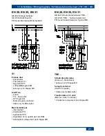
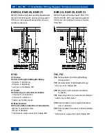
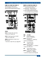
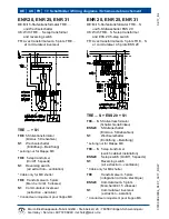
Connect the unit electrically


 wiring diagrams on page 21...24. 


Cut off and insulate PE 

conductor and individual cable 

cores that are not required! 

Wire up electrics for fan on terminal 

block [5] and for shutter on terminal block 

[6] 

 relevant wiring diagram. With 

airstream-operated Maico AS shutter, 

there are no connections on terminal 

block [6]. 


The degree of protection is only 

guaranteed if the cables are fed 

through correctly using the inten-

ded cable grommets [T1]…[T5]. 

11.  Check protective-conductor opening on 

housing. 

12.  Attach terminal box cover [2] and screw 

down (tightening torque of the 3 screws 

is 1 Nm each) 

 Fig. 2H. Ensure the 

sealing [2.1] is fitted correctly. 

13.  If necessary, connect a speed controller 

(ST, STU, STS) or frequency converter.  


The technology used in the 

phase angle controller may 

cause humming noises. If using a 

frequency converter, you may 

need to use a mains filter. 

14.  Fit internal cover [1]. To do this, hang 

internal cover [3] on the top of the 

connecting flange [3], swivel down and 

clip it into place in the safety catch. Do 

not twist it. 

15.  Switch the mains fuse on. Run function 

test. 


10.2 Ceiling mounting (not shown) 

1.  Carry out the ceiling installation as 

described in the wall mounting section. 


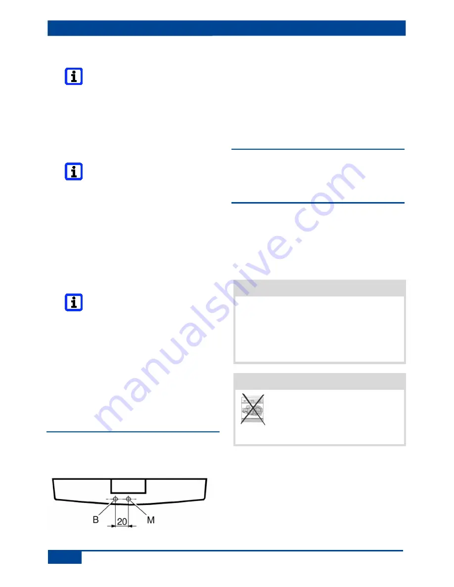
2.  Drill through the internal cover [1] at 

position [B] carefully and with a suitable 

drill bit (Ø 3.5 mm). 

The hole prevents 

the build-up of damp and bacteria in 

the fan housing. Observe dimensions.


3.  Secure the internal cover [1] with the 

supplied screw at marking [M]. 3 x 10 mm 

screw is secured in the internal cover with 

sticky tape. 


10.3 Mounting on pitched roofs  

(not shown) 

See Chapter 10.2, Ceiling mounting. 
 

11. Cleaning 

Clean fan with dry cloth only. If necessary, 

use a vacuum cleaner. If possible, swivel the 

lamellae upwards to clean the shutter. 

Do not use aggressive, harmful or easily 

flammable cleaning agents for cleaning work. 


NOTICE


The internal cover will be damaged if 

the internal grille is pulled 


 Remove internal cover from connecting 

flange [3] as shown in Figure 2C. Under no 

circumstances pull it off by the internal grille 

or its top. 


NOTICE


The internal cover will be 

damaged if cleaned in a  

dishwasher 

 Do not clean internal cover in a 

dishwasher. 


1.  Take off internal cover [1] (no tools 

needed). 

2.  Clean the internal parts with a dry cloth. 
3.  Position internal cover [1] as shown in 

Figure 2H. 


Summary of Contents for EN 25

Page 1: ...Wandeinbauventilatoren Mounting and Operating instructions Wall mounted fans Instructions de montage et Mode d emploi Ventilateurs muraux encastrables EN 20 EN 25 EN 31 ENR 20 ENR 25 ENR 31 www m aic...

Page 2: ...EN ENR Abmessungen Dimensions A B C D E EN 20 55 103 212 320 268 EN 25 55 103 266 370 315 EN 31 60 126 320 445 375 ENR 20 55 103 212 320 268 ENR 25 55 103 266 370 315 ENR 31 60 126 320 445 375...

Page 3: ......

Page 4: ......

Page 5: ......

Page 6: ...chulung und Erfahrung die einschl gigen Normen und Richtlinien kennen die elektrischen Anschl sse gem beigef gtem Verdrahtungsplan fachgerecht und sicher ausf hren k nnen und Risiken und Gef hrdungen...

Page 7: ...igen und warten lassen welche die Gefahren dieser Arbeiten sicher erkennen und vermeiden k nnen Verletzungsgefahr durch Saugwirkung des Ventila tors und drehendes Fl gelrad Haare Kleidung Schmuck etc...

Page 8: ...x 1 5 mm je nach Ger tetype anschlie en Ger te nur mit auf Typenschild angege bener Spannung und Frequenz betreiben Die auf dem Typenschild angegebene Schutzart ist nur gew hrleistet bei bestim mungsg...

Page 9: ...inzelnen Adern gem Schaltbild in Kapitel 17 verdrahten 10 Montage 10 1 Wandmontage Abb 2A bis 2H 1 Netzsicherung ausschalten gegen Wiedereinschalten sichern und ein Warnschild anbringen 2 D bell cher...

Page 10: ...alten Funktionstest durchf hren 10 2 Deckenmontage ohne Abb 1 Den Deckeneinbau wie unter Wandeinbau beschrieben vornehmen 2 Innenabdeckung 1 an Position B vor sichtig und mit geeignetem Bohrer 3 5 mm...

Page 11: ...im Ge h use durch staubhaltige Luft Elektrofachkraft hinzu ziehen Innenraum auf keinen Fall mit Wasser oder Hochdruckreiniger reinigen Besteht die St rung weiterhin oder tritt diese wiederholt auf de...

Page 12: ...standards and guidelines can competently and safely connect units to an electrical power supply in line with the attached wiring diagram and are able to recognise and avoid risks and dangers associate...

Page 13: ...associated with this work Danger of injury due to suction from fan and rotating impeller Hair clothing jewellery etc may be pulled into the fan if you get too close to it During operation always keep...

Page 14: ...n unit type cables The units may only be operated using the voltage and frequency shown on the rating plate The degree of protection stated on the rating plate is only guaranteed if installation is un...

Page 15: ...wire the individual cable cores in accordance with the wiring diagram in Chapter 17 10 Mounting 10 1 Wall mounting Figures 2A to 2H 1 Switch off mains fuse secure against being accidentally switched...

Page 16: ...twist it 15 Switch the mains fuse on Run function test 10 2 Ceiling mounting not shown 1 Carry out the ceiling installation as described in the wall mounting section 2 Drill through the internal cove...

Page 17: ...nces should the inside of the unit be cleaned with water or a high pressure cleaner If the fault still continues or occurs again disconnect the fan from the power supply at all poles Let a certified e...

Page 18: ...ssances et d exp rience dans la technique de ventilation est autoris effectuer le montage Les travaux sur le syst me lectrique ne doivent tre ex cut s que par des lectriciens qualifi s On entend par l...

Page 19: ...sont diffus s dans les pi ces par le ventilateur Ne jamais utiliser le ventilateur pour diffuser des produits chimiques ou gaz vapeurs agressifs Des vapeurs de graisse et d huile en provenance de hot...

Page 20: ...d alimentation lectrique d sactiver le fusible secteur s curiser contre toute remise en service intempestive et apposer un panneau d avertissement de mani re bien visible N utiliser le ventilateur qu...

Page 21: ...ionnement en raison du frottement de l h lice 8 Installer le manchon d assemblage 3 ni gauchi ni coinc Pr voir un support plan Risque de court circuit Endommage ment de l appareil par formation de con...

Page 22: ...rnier Pour que l humidit ne puisse pas rentrer dans le bornier percer le manchon en rond un peu plus petit que le c ble de raccordement Le manchon de c ble doit enserrer troitement le c ble de raccord...

Page 23: ...Dommage sur le capot int rieur si celui ci est nettoy dans un lave vaisselle Ne pas nettoyer le capot int rieur dans un lave vaisselle 1 Retirer le capot int rieur 1 aucun outil n est n cessaire 2 Net...

Page 24: ...ndiquer les donn es suivantes 1 N d impression du pr sent mode d emploi 0185 0992 0004 2 N de plaque signal tique X sur le c t de la plaque 3 N de position selon la figure 1 Adresse de commande Maico...

Page 25: ...ity controller Cable only for MK shutter Marche Arr t par interrupteur thermostat TH hydrostat HY5 r gulateur de la qualit par l air EAQ Conducteur uniquement pour trappe MK EN 20 EN 25 EN 31 DE Mit 5...

Page 26: ...hutter S1 Marche Arr t S2 Commutation extraction d air a ration Borne 5 extraction d air Borne 6 a ration Conducteur uniquement pour trappe MK ENR 20 ENR 25 ENR 31 DE Mit Stufen Wendeschalter FS6 FS7...

Page 27: ...K ENR 20 ENR 25 ENR 31 DE Mit 5 Stufentransformator TRE und Wendeschalter W1 WU1 UK With TRE 5 step transformer and W1 WU1 reversing switch FR Avec transformateur 5 plots TRE et commutateur inverseur...

Page 28: ...ormator TRE S und 5 Stufenschalter ESS 20 UK With TRE S 5 step transformer and ESS 20 5 step switch FR Avec transformateur 5 plots TRE S et commutateur 5 plots ESS 20 TRE S ESS 20 S1 TRE S 5 Stufentra...

Reviews: