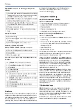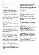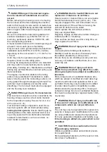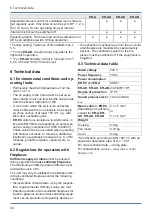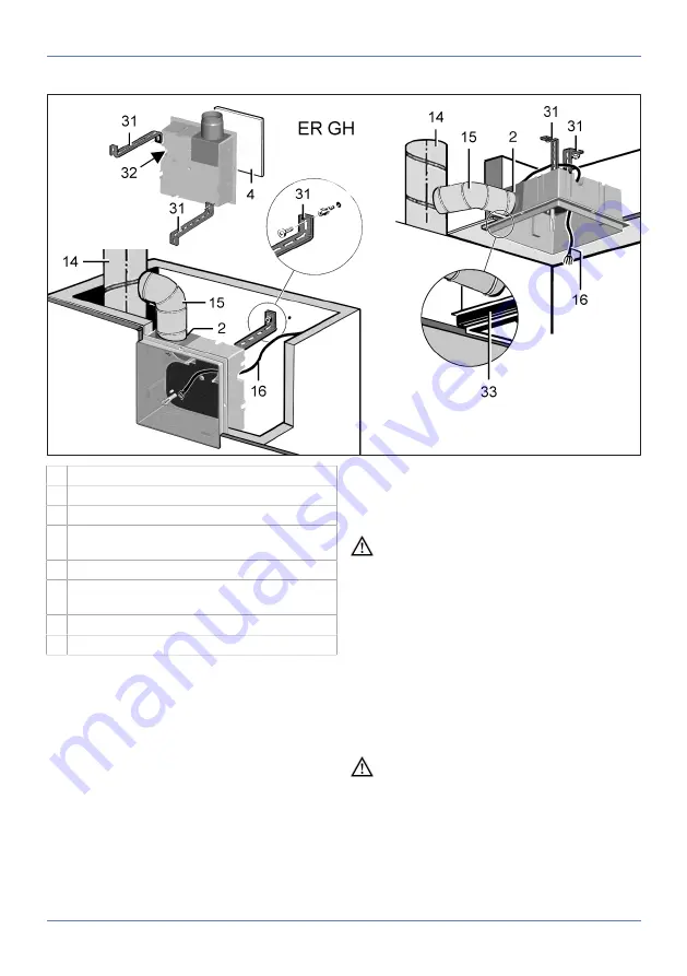
8 Housing installation
42
8.4 Wall installation, single room
2 Exhaust socket with plastic shutter
4 Plaster protective cover
14 Main duct, steel folded spiral-seams duct
15 Connection duct, AFR 80 DN 75/80 flexible
aluminium duct
16 Power cable
31 Mounting support UPM 60/100 or ER-UPM (2
items)
32 Stepped grommet
33 ER-MO expanded rubber
1. Remove the plaster protective cover from the
housing.
NOTICE The unit will be damaged and func-
tion impaired if the fixing screws used are in-
correct/too long.
Fixing screws may not penetrate into the hous-
ing.
Use the screws provided (
UPM 60/100
mounting
support).
2. Cut the mounting support to the required
length, bend it into shape and fix it to the
housing with the supplied fixing screws.
3. Mark fixing holes for mounting support on rear
shaft wall, produce holes and insert dowels.
Suitable mounting material is to be provided
by the customer.
DANGER Danger of short-circuits and
damage to the unit.
If the stepped grommet is not installed correctly,
water may penetrate the housing. The degree of
protection can no longer be guaranteed.
Drive through stepped grommet so that it can
seal the cable sheathing all the way round (circu-
lar, not a slot).
4. Insert power cable from rear of housing
through stepped grommet into housing.
5. Insert the housing with the mounting support
into the shaft and fix it to the rear wall of the
shaft.
DANGER Fire may spread if connection
duct is incorrectly installed.
Only use permitted duct material (
).
Correctly attach connection duct to exhaust
socket.
6. Connect connection duct to exhaust socket
sealed for ventilation, e.g. with cold-shrink
tape.


