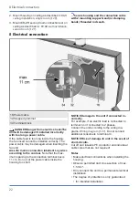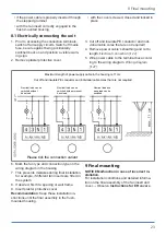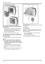
6 Mounting preparations
13
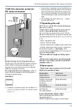
6.2 Preparations for wall installation
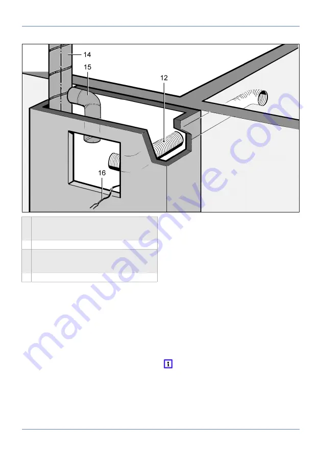
12 Suction duct for second room connection on
ER GH: AFR 75/AFR 80 flexible aluminium
duct
14 Main duct: Steel folded spiral-seams duct
15 Connection duct on ER GH: AFR 75/AFR 80
flexible aluminium duct permitted inside the
shaft
16 Power cable
Installation information
• Observe approval:
and
Requirements in line with approval [
.
• Always use correct duct material for the hous-
ing.
• For fire protection systems, the gap remaining
between the connection duct and brickwork/wall
boards/wall/ceiling must be fully sealed with
non-flammable materials that are resistant to
deformation (e.g. concrete, cement mortar, fire
protection filler).
NOTICE Damage to unit, malfunctioning in the
event of corrosion damage from mortar.
Wrap ventilation ducts, connected to the unit,
with a suitable adhesive tape to protect against
corrosion inside the brickwork, e.g. using cold-
shrink tape.
Preparing the shaft
1. Produce opening in shaft or alternatively pro-
duce a wall facing. Ensure a suitable, flat sur-
face for the housing so that the fan insert can
be safely inserted in the housing later on.
2. For a second room connection, produce an
opening in the wall or shaft for the suction
duct. Note permissible housing installation po-
sitions.
3. Correctly attach main duct inside the shaft.
4. For fire protection systems, use ceiling com-
pound. To do this, encase the ceiling and pour
in the material from above.
5. Connect connection duct, suitable for the
housing, to the main duct and seal for ventila-
tion.
6. Cut connection duct to length, note a max-
imum duct length of 6 m.
Cut connection duct to a length which al-
lows it to be fitted on the exhaust socket
and also sealed for ventilation at the unit
end.
7. Lay suction duct and seal gap remaining cor-
rectly as described in previous mounting in-
structions.
Summary of Contents for ER shell
Page 4: ...Overview of ER EC system 4 Overview of ER EC system...
Page 29: ...Notes...
Page 30: ......
Page 31: ......


