14 Dismantling
27
Air filter
ZF EC+ replacement air filter for ER-A
Article no. 0093.0610
• 5x ZF EC+ replacement air filter (filter class G2)
• 5x filter change indicator (TimeStrip)
Large pack of ZF EC+ replacement air filters
for ER-A
Article no. 0093.0611
• 100x ZF EC+ replacement air filters (filter class
G2)
• 100x filter change indicator (TimeStrip)
ZF EC replacement air filter for ER-AK, ER-AH
and ER-AB
Article no. 0093.0758
• 5x ZF EC replacement air filters (filter class G2)
Large pack of ZF EC replacement air filters for
ER-AK, ER-AH and ER-AB
Article no. 0093.0759
• 100x ZF EC replacement air filters (filter class
G2)
ZRF replacement air filter for ER-ZR second
room connection set
Article no. 0093.0923
• 5x replacement air filters for internal grille ER-
ZR second room extraction (filter class G2)
ZF ECD replacement permanent filter for ER-
AK, ER-AH and ER-AB
Article no. 0093.1561
• 2x replacement permanent filters for covers of
the ER EC fan unit (filter class G2)
ZF ECD+ replacement permanent filter for ER-
A
Article no. 0093.1562
• 2x replacement permanent filters for covers of
ER EC fan unit (filter class G2)
• 10x filter change indicator (TimeStrip)
14 Dismantling
Dismantling may only be undertaken by a
qualified electrician: Specialist installer qualifica-
tions [
1. Before accessing the connection terminals,
shut down all supply circuits (switch off mains
fuse), secure against being accidentally
switched back on and position a visible warn-
ing sign.
2. Remove fan insert.
3. Remove all cables.
4. Remove flush-mounted housing from wall.
15 Environmentally responsible
disposal
The ventilation unit and the packaging contain
parts that can be recycled, and should not end up
in the domestic waste.
Dispose of the
packaging material
in an environ-
mentally-friendly way, in compliance with the reg-
ulations valid in the country where you are.
Dispose of the
air filter
in an environmentally-
friendly way, in compliance with the regulations
valid in the country where you are.
At the end of its service life, dispose of the
unit
in
an environmentally-friendly way, in compliance
with the regulations valid in the country where you
are.
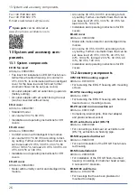
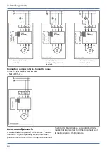
16 Wiring diagram
Wiring diagrams
Tolerances for the stated times = nominal
value ± 5 %
Values that can be set with optional cover with in-
tegrated electronics:
• ER-AK, ER-AH, ER-AB: Start delay and over-
run time
• ER-AH: Humidity control
• ER-AH: Motion detector
For ER-A cover:
• Start delay of 60 seconds
• Overrun time of 15 minutes.
Connection variants, base load/full load for
ER-A, ER-AK, ER-AH and ER-AB
Summary of Contents for ER shell
Page 4: ...Overview of ER EC system 4 Overview of ER EC system...
Page 29: ...Notes...
Page 30: ......
Page 31: ......


