4 System and product information
8
NOTICE Non-intended operation/impermiss-
ible operation due to incorrectly mounted
unit.
Only install unit in accordance with the planning
documents.
In particular, note the information on ventilation
channels and sound deadening.
Observe planning instructions regarding unit pos-
ition and distance to other façade components.
If necessary, use isolating elements.
4 System and product informa-
tion
4.1 Certificates of approval
Certificates of approval on request.
4.2 Installation conditions
If installed in accordance with DIN 18017-3,
use is only permitted:
• in single air extraction systems with a common
main duct;
• with an air supply via shaft or duct;
• with permitted connection ducts;
• with the ER EC housing suited to the system;
• if correctly installed as per the instructions in
this manual and national technical approval;
• with sufficient space from the wall or ceiling;
• if unit is completely installed;
• with the correct air filters;
• with the outside air openings stated in the plan-
ning documents.
• with flush-mounted installation in the wall or
ceiling.
If the installation deviates from DIN 18017-3:
• ER EC fans can also be used as standalone
units.
• Installation in the wall or ceiling is permitted.
• The extraction of an additional room (open plan
kitchen etc.) or a toilet seat air extraction is per-
mitted.
4.3 Permitted exhaust air systems
The ER EC single air extraction system can be
used in combination with a
ceiling barrier sys-
tem
inside and outside the shaft.
A fan connection duct, made of flexible aluminium
duct, is also prescribed for a second connection.
Use in an air extraction system is permissible
without protection requirements
.
4.4 Possible combinations
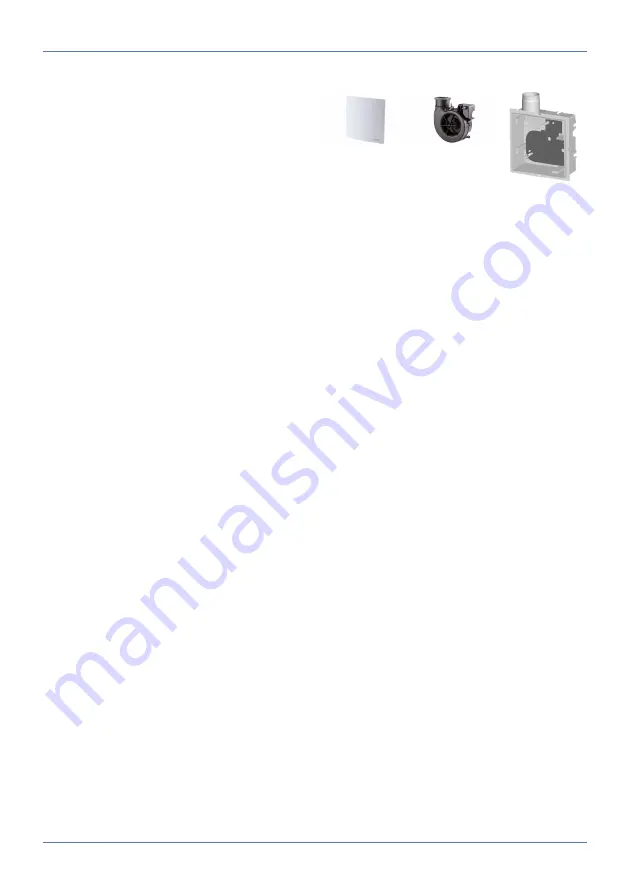
ER-A
ER-AK
ER-AH
ER-AB
ER EC
ER GH
In the
shell construction phase
the ER GH
flush-mounted housings are installed, electrically
wired and provided with a plaster protective
cover.
In combination with the second room connection
set (ER ZR) and the ER-AS extraction socket, the
ER EC can also be used for toilet seat air extrac-
tion (extraction via flushing pipe).
Final mounting
is undertaken once the plaster-
ing and paint work is complete: Place the fan in-
sert into the housing and attach the cover with air
filter. For covers ER-AK, ER-AH and ER-AB, ad-
just the setting values as necessary.
ER GH flush-mounted housing
• DN 75 or DN 80 connection diameter.
• Plastic housing without fire protection equip-
ment. Can be combined with ceiling barrier sys-
tem.
• Sealed housing with water jet protection for
areas 1 (IP X5).
• For the wall or ceiling installation, inside or out-
side the exhaust air shaft.
• Permissible air outlet direction with wall installa-
tion upwards, to the right, to the left or to the
rear.
• Turn air outlet to the right or left by turning the
housing by 90°.
• Plastic exhaust socket with airstream-operated
plastic shutter, maintenance-free.
• Fix exhaust socket in housing, can be conver-
ted for air outlet at rear without tools.
• Easy-to-install snap-fit fasteners for fastening
the fan insert.
• For the connection sockets of a toilet seat air
extraction or a second room connection, knock-
out point at bottom.
Summary of Contents for ER shell
Page 4: ...Overview of ER EC system 4 Overview of ER EC system...
Page 29: ...Notes...
Page 30: ......
Page 31: ......


