6 Mounting preparations
17
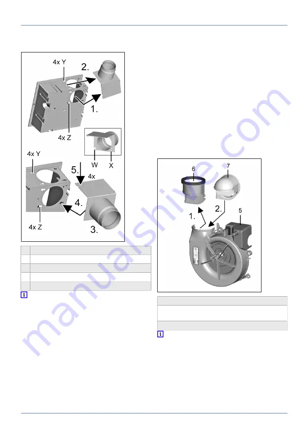
6.6 Conversion of exhaust socket for
air outlet towards rear
3 Shutter
Z Positions
X 4 locking bolts
W 4 bayonet hooks
Y 4 slots
Before the conversion, pull the shutter out
of the exhaust socket.
1.
Fig. at top:
At the 4 positions, loosen (pull off)
the 4 locking bolts (push buttons) on the ex-
haust socket.
2. Push the 4 bayonet hooks in the exhaust
socket at the side into the 4 slots to the right
and remove the exhaust socket.
3.
Fig. at bottom:
Rotate the exhaust socket so
that it is pointing to the rear.
4. Place the exhaust socket onto the housing
and push with the 4 bayonet hooks (at rear) to
the right into the slots right up to stop.
5. Push the 4 push buttons into the housing
holes on the upper side of the housing at posi-
tions [Y]. These must audibly engage.
NOTICE If the air exhaust socket is installed
incorrectly, the function of the unit is im-
paired.
Ensure that all locking bolts and push buttons are
engaged and that the socket is flush with the
housing.
6. Check for correct installation of the exhaust
socket.
7. Insert the shutter into the exhaust socket as
described in the
Left air outlet direction
in-
stallation position:
.
6.7 Conversion of air outlet adapter
for air outlet towards rear
5 Spiral housing
6 Air outlet adapter: Air outlet above (factory
setting)
7 Air outlet adapter: Air outlet at rear
For air outlet direction to the rear, replace
the air outlet adapter with the curved air out-
let adapter.
Replacement
1. Loosen the 2 locking tabs of the exhaust
socket and carefully pull it out of the spiral
housing rearwards.
Summary of Contents for ER shell
Page 4: ...Overview of ER EC system 4 Overview of ER EC system...
Page 29: ...Notes...
Page 30: ......
Page 31: ......


