background image

7 Housing installation

20

7. Provide unit with electrical connection: 

Elec-

trically connecting the unit [

}

 23]

.

8. Insert the plaster protective cover in the hous-

ing.

9. Plaster in housing flush with front edge, note

tile thickness if necessary: 

Important informa-

tion about plastering [

}

 18]

.

7.5 ER GH ceiling installation, single
room

1. Remove the plaster protective cover from the

housing.

NOTICE The unit will be damaged and func-
tion impaired if the fixing screws used are in-
correctly / too long.

Fixing screws may not penetrate into the hous-
ing.
Use screws provided (mounting support
UPM 60/100).

2. For suspended ceilings, cut mounting support

to the required length, bend it into shape and
fix it to the housing (

ER GH wall installation,

single room [

}

 19]

).

3. Mark fixing holes for mounting support/hous-

ing on ceiling, produce holes and insert dow-
els. Suitable mounting material is to be
provided by the customer.

 DANGER Danger of short-circuits and

damage to the unit.

If the stepped grommet is not installed correctly,
water may penetrate the housing. The degree of
protection can no longer be guaranteed.
Drive through stepped grommet so that it can
seal the cable sheathing all the way round (circu-
lar, not a slot).

4. Insert power cable from rear of housing

through stepped grommet into housing.

5. Move housing into desired position and secure

to ceiling with/without mounting support.

 DANGER Fire may spread if connection

duct is incorrectly installed.

Only use permitted duct material (

Requirements

in line with approval [

}

 12]

).

Correctly attach connection duct to exhaust
socket.

6. Connect connection duct to exhaust socket

sealed for ventilation, e.g. with cold-shrink
tape.

7. Provide unit with electrical connection: 

Elec-

trically connecting the unit [

}

 23]

.

8. Insert the plaster protective cover in the hous-

ing.

9. Plaster in housing flush with front edge.

Summary of Contents for ER shell

Page 1: ...Installation instructions for ER shell ER EC flush mounted exhaust air systems according to DIN 18017 3 ER GH flush moun ted box for ER EC systems www maico ventilatoren com...

Page 2: ...the electrical connection 16 6 5 Preparing the shutter 16 6 6 Conversion of exhaust socket for air outlet towards rear 17 6 7 Conversion of air outlet adapter for air outlet towards rear 17 7 Housing...

Page 3: ...of delivery ER GH flush mounted housing Article no 0084 0350 Flush mounted plastic housing with exhaust socket DN 75 DN 80 no fire protection Plastic shutter Plaster protective cover Installation and...

Page 4: ...Overview of ER EC system 4 Overview of ER EC system...

Page 5: ...accordance with the national technical approval Only a qualified electrician is permitted to work on the electrics You are deemed a qualified elec trician if you are familiar with the relevant stand a...

Page 6: ...sly conveying steam saturated air Never use unit to convey steam saturated air NOTICE Damage to the unit due to imbalance of the impeller when conveying solid particles Never use unit to convey solid...

Page 7: ...flammable materials resistant to deformation such as concrete ce ment mortar or plaster WARNING Risk to health if filters are not replaced or if there are no air filters Heavily soiled or moist air fi...

Page 8: ...barrier sys tem inside and outside the shaft A fan connection duct made of flexible aluminium duct is also prescribed for a second connection Use in an air extraction system is permissible without pr...

Page 9: ...r NYM J 3 x 1 5 or 5 x 1 5 mm depending on the cover variant ER EC fan insert Fan insert for installation in housing Electrical plug connection for quick installation in the housing Energy saving EC m...

Page 10: ...20 m h 30 m h 40 m h or 100 m h Full load level on off via light switch or separate switch During manual operation e g using light switch the start delay and overrun time apply Full load operation 60...

Page 11: ...in residential units with air ventilated fireplaces under the following conditions the evaluation criteria drawn up by the respons ible regional master chimney sweep are met Parallel operation of air...

Page 12: ...on nections Connection diameter DN 75 or DN 80 Shaft wall Any board material Connection ducts inside the shaft E g AFR 80 flexible aluminium duct between main duct in shaft and ER unit max 2 m long ap...

Page 13: ...ted to the unit with a suitable adhesive tape to protect against corrosion inside the brickwork e g using cold shrink tape Preparing the shaft 1 Produce opening in shaft or alternatively pro duce a wa...

Page 14: ...eel folded spiral seams duct 15 Connection duct on ER GH AFR 75 AFR 80 flexible aluminium duct 16 Power cable Be sure to note the approval and installa tion information Preparations for wall installa...

Page 15: ...bolt 27 2 Metal expansion dowel 28 Retaining bolt with nut 29 Retaining bolt 30 Steel clamping band Be sure to note the approval and installa tion information Preparations for wall installa tion 13 Du...

Page 16: ...cal data Technical data 10 Observe permitted duct cross section of max 1 5 mm 1 Lay power cable to the installation location 2 Continue with the safety test of the release device Preparing the shutter...

Page 17: ...he housing holes on the upper side of the housing at posi tions Y These must audibly engage NOTICE If the air exhaust socket is installed incorrectly the function of the unit is im paired Ensure that...

Page 18: ...ion and non suspended ceil ing Mounting directly on the ceiling Suitable mounting material is to be provided by the customer The plastic shutter should be prepared ac cording to these instructions so...

Page 19: ...screws 3 Mark fixing holes for mounting support on rear shaft wall produce holes and insert dowels Suitable mounting material is to be provided by the customer DANGER Danger of short circuits and dama...

Page 20: ...s and insert dow els Suitable mounting material is to be provided by the customer DANGER Danger of short circuits and damage to the unit If the stepped grommet is not installed correctly water may pen...

Page 21: ...alla tion socket is inserted incorrectly 11 1 Degree of protection is no longer guaranteed Correctly insert installation socket up to stop This must audibly engage 2 Place installation socket in housi...

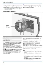
Page 22: ...fan unit Area for mains connection labelled Lay wires according to the contour Note that the max imum spacing to the connection terminal box is 11 cm Do not cut the power cable inside the housing too...

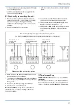
Page 23: ...7 Maximum length of power supply cable in the housing is 11 cm Cut off and insulate PE conductor and individual cable cores that are not required Nominal load can be switched without base load Nominal...

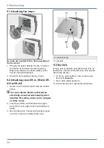
Page 24: ...ew The covers ER AK ER AH and ER AB are electrically connected automatically when installed The setting values can be changed on these covers 2 Insert the air filter and fold down the upper part of th...

Page 25: ...ase load opera tion factory setting A light switch or separate switch can be used to switch to full load operation with 60 m h The unit control is located in the cover ER AK ER AH and ER AB have autom...

Page 26: ...e 30 m h 60 m h according to fact ory setting Further volumetric flows that can be set base load 20 m h 30 m h 40 m h full load 60 m h 100 m h Installation and operating instructions for ER covers ER...

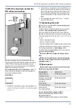
Page 27: ...ng Dismantling may only be undertaken by a qualified electrician Specialist installer qualifica tions 5 1 Before accessing the connection terminals shut down all supply circuits switch off mains fuse...

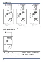
Page 28: ...d optional optional optional Connection variants interval humidity move ment for ER AK ER AH ER AB Not for ER A Motor control Acknowledgements Maico Elektroapparate Fabrik GmbH Transla tion of the ori...

Page 29: ...Notes...

Page 30: ......

Page 31: ......

Page 32: ...Maico Elektroapparate Fabrik GmbH Steinbeisstr 20 78056 Villingen Schwenningen Deutschland Service 49 7720 6940 info maico de D04 21_EN_DSW AS AV...

Reviews: