9 Final mounting
23
• if the power cable is properly inserted through
the stepped grommet
• with the fan insert correctly engaged in the
flush-mounted housing
• with the cover screwed, closed and locked in
place
8.1 Electrically connecting the unit
1. Prior to accessing the connection terminals,
switch off all supply circuits. Switch off mains
fuse, secure against being accidentally
switched back on and position a visible warn-
ing sign.
2. Remove plaster protective cover.
3. Cut off and insulate PE conductor and indi-
vidual cable cores that are not required!
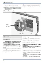
4. Remove power cable’s sheathing and cut to
.
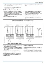
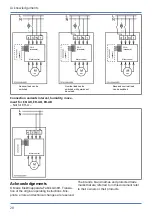
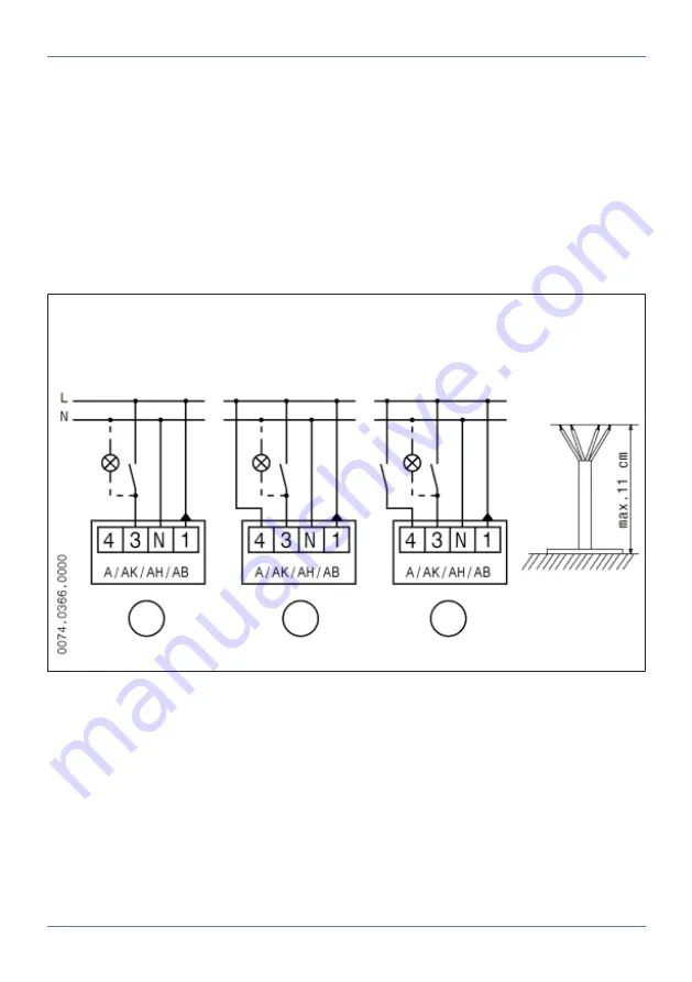
5. Wire power cable to the terminal box accord-
Maximum length of power supply cable in the housing is 11 cm.
Cut off and insulate PE conductor and individual cable cores that are not required
Nominal load can be
switched without
base load
Nominal load can be
switched with permanent
base load
Nominal load and
base load can be
switched
Please tick the connection variant
6. Mark the fan type and connection type on the
wiring diagram in the housing.
7. This prevents mistakes during final installation,
for example, if different fan inserts are fitted in
the system.
8. If desired, first fit a spacing or wall frame.
9. Insert plaster protective cover.
Recommendation
: Keep these installation in-
structions until the final assembly in the flush-
mounted housing.
9 Final mounting
NOTICE Malfunction in case of incorrect in-
stallation.
For installation conditions and detailed informa-
tion on the final assembly of the fan insert and
cover → Observe
Instructions for ER covers
.
Summary of Contents for ER shell
Page 4: ...Overview of ER EC system 4 Overview of ER EC system...
Page 29: ...Notes...
Page 30: ......
Page 31: ......


