background image

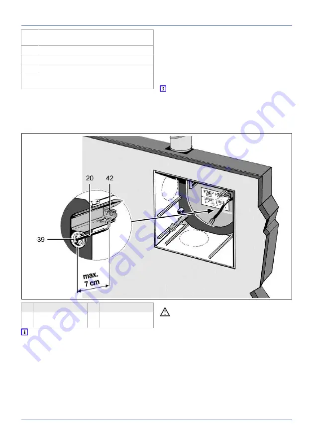
8 Electrical connection

28

5.1

Steel connection socket DN 75/80 for
second room extraction on ER-UPB

6

Protective grille

7

Filter mat filter class G2

8

Adapter

9

9 Suction duct, second room connection:
Steel folded spiral-seams duct DN 75/80

1. Install housing as described in these instruc-

tions.

2. Secure suction duct and steel socket with 3

steel blind rivets or steel screws and connect
sealed for ventilation.

3. Produce fixing holes for adapter and insert

dowels.

4. Connect adapter fully sealed to suction duct,

e.g. with cold-shrink tape.

5. Secure adapter to the wall with screws.

6. Insert filter mat and fit protective grille in the

correct position.

 With second room extraction, keep regulat-

ing plate somewhere safe for the final installa-
tion. This is needed to operate the ER 100 fan
insert and is inserted in the cover.

8 Electrical connection

20 Power cable

39 Cable grommet

42 Connection ter-

minal

 To prevent the unit and/or electric compon-

ents from malfunctioning as a result of reverse
polarity voltages and induction (incorrect igni-
tion or glowing/flaring of LED, energy-saving
or neon lamps), the unit and electric compon-
ents connected in parallel, such as room light-
ing, should be connected via a double-pole
switch.

 DANGER Danger to life from electric

shock.

Prior to accessing the connection terminals,
switch off all supply circuits. Switch off mains
fuse, secure against being accidentally switched
back on and position a visible warning sign.

Summary of Contents for ER-UP/G

Page 1: ...Installation and operating instructions Flush mounted exhaust air systems according to DIN 18017 3 ER UP G ER UPD ER UPB ER 60 ER 100 Centro M Centro E Centro H ...

Page 2: ...nstallation 17 7 1 Installing ER UP G housing 17 7 2 Installation information for ER UP G housing 18 7 3 Important information about plas tering 18 7 4 ER UP G wall installation single room 18 7 5 ER UP G ceiling installation single room 20 7 6 ER UP G wall installation second room 21 7 7 ER UP G ceiling installation second room 22 7 8 Installation of ER UPD housing 22 7 9 Installation information...

Page 3: ...Table of contents 3 15 Spare parts 35 16 Removal 36 17 Environmentally responsible disposal 36 18 Wiring diagrams 37 ...

Page 4: ...st time Follow the in structions Pass these instructions on to the owner for safekeeping Overview of UPG system ER UP G with plastic shutter without fire pro tection equipment 1 Plastic backflow preventer Fig of installation position with air outlet dir ection to the right 2 Plastic exhaust socket ...

Page 5: ...mitted to work on the electrics You are deemed a qualified elec trician if you are familiar with the relevant stand ards and guidelines can competently and safely connect units to an electrical power supply in line with the Wiring diagrams 37 and are able to recognise and avoid risks and dangers associ ated with electricity on the basis of your technical training and experience 2 Intended use Thes...

Page 6: ...e unit when not fully mounted Electric components are a potential source of electric shock If the unit is open all off the supply circuits must be switched off mains fuse off secured against being accidentally switched back on and a visible warning sign must be attached Only operate the unit when it is completely in stalled DANGER Danger if the relevant regula tions for electrical installations ar...

Page 7: ...bstances mould germs etc This may also happen if the unit is shut down for an extended period If the air filter is missing the unit and air ducts become soiled Never operate the unit without air filters Only use original filters Regularly change air filter when a filter change is indicated LED or TimeStrip If the unit has not been used for a long time al ways replace the air filters WARNING Risk o...

Page 8: ...system ER UP G ER UPD ER UPB PAM GLOBAL RML cast ventilation sys tem no yes yes Ceiling barrier sys tem yes no no System with fire proof shaft no yes yes Air extraction system without fire protection yes no no ER UP G can be used inside and outside the shaft connection duct made from flexible alu minium duct second room connection made from flexible aluminium duct ER UPD can be used inside and out...

Page 9: ...soldered strut For connecting second room ventilation with knockout points at bottom on right and left 4 4 4 Flush mounted housing ER UPB Housing with maintenance free fire protection shut off device to prevent fire transmission K90 18017 Housing with fire protection cover for use in fire proof exhaust air shafts Suitable for wall or ceiling installation in a fire proof exhaust air shaft Permissib...

Page 10: ...rier free With humidity control Overrun time controlled by program min 15 minutes at full load Can also be operated manually with optional switch Not suitable for second room ventilation D model In combination with three step switch with 3 power levels 35 60 or 100 m h Can be used in combination with supply air elements for controlled domestic ventilation RC model with radio electronics Use in rad...

Page 11: ...ir intake must be ensured during operation with air ventilated fireplaces The maximum permitted pressure difference per residential unit is 4 Pa The unit may only be installed in residential units with air ventilated fireplaces under the following conditions the evaluation criteria drawn up by the respons ible regional master chimney sweep are met Parallel operation of air ventilated fireplaces fo...

Page 12: ... AFR 80 or steel folded spiral seams duct between main duct in shaft and ER unit max 2 m long ap proval Flexible alu minium duct AFR 80 or steel folded spiral seams duct between main duct in shaft and ER unit max 2 m long ap proval Steel fol ded spiral seams duct between ER unit and second room connection Connection ducts outside the shaft E g AFR 80 flexible alu minium duct between main duct in s...

Page 13: ...ll boards wall ceiling must be fully sealed with non flammable materials that are resistant to deformation e g concrete cement mortar fire protection filler NOTICE Damage to unit malfunctioning in the event of corrosion damage from mortar Wrap ventilation ducts connected to the unit with a suitable adhesive tape to protect against corrosion inside the brickwork e g using cold shrink tape Preparing...

Page 14: ... preparations 9 Suction duct for second room connection on ER UP G Flexible aluminium duct AFR 75 AFR 80 ER UPD Flexible aluminium duct AFR 75 AFR 80 or steel folded spiral seams duct DN75 DN80 ER UPB Steel folded spiral seams duct DN75 DN80 18 Main duct Steel folded spiral seams duct 19 Connection duct on ER UP G Flexible aluminium duct AFR 75 AFR 80 ER UPD Steel folded spiral seams duct DN75 DN8...

Page 15: ...anchor bolt 31 2 Metal expansion dowel 32 Retaining bolt with nut 33 Retaining bolt 34 Steel clamping band Be sure to note the approval and installa tion information Preparations for wall installa tion Duct attachment with duct clamp alternatively duct attachment with clamping band Ensure a spacing of max 1 5 m between the duct attachments 1 Correctly attach main duct inside the shaft 2 For fire p...

Page 16: ...ec trical installations and when fitting equipment In Germany observe DIN VDE 0100 and the cor responding parts in particular Observe ambient conditions Environmental conditions and operating limits and technical data Technical data 11 Observe permitted duct cross section of max 1 5 mm 1 Lay power cable to the installation location 2 Continue with the safety test of the release device Preparing th...

Page 17: ...NOTICE The fire protection shut off device is permanently closed if there is no soldered strut Air extraction is then no longer possible Check that the soldered strut is inserted correctly before installation The functionality of the re lease mechanism must be ensured so that the shut off shutter also opens in normal operation NOTICE Unpleasant smells from the main duct The fire protection shut of...

Page 18: ...e rating plate is no longer ensured Break open the housing segment S below to use the ER ZR second room connection set or the ER AS extraction socket A toilet seat air extraction unit is connected to the housing using the ER AS extraction socket DN 75 80 The toilet seat air extraction unit must not be connected to the second room connection socket or the Centro exhaust air element Use ER MO expand...

Page 19: ... and insert dowels Suitable mounting material is to be provided by the customer DANGER Danger of short circuits and damage to the unit If the cable grommet is not installed correctly wa ter may penetrate the housing The degree of protection can no longer be guaranteed Drive through cable grommet so that it can seal the cable sheathing all the way round circular no slots 4 Guide power cable from re...

Page 20: ...d ceilings cut mounting support to the required length bend it into shape and fix it to the housing ER GH wall installation single room 3 Mark fixing holes for mounting support hous ing on ceiling produce holes and insert dow els Suitable mounting material is to be provided by the customer DANGER Danger of short circuits and damage to the unit If the cable grommet is not installed correctly wa ter...

Page 21: ...ing a knife NOTICE The unit will be damaged function will be impaired by incorrect air if the installa tion socket is inserted incorrectly 11 1 Degree of protection is no longer guaranteed Correctly insert installation socket up to stop This must audibly engage 2 Place installation socket in housing The edge of the socket must click into place on the wall of the housing 3 Install housing as descri...

Page 22: ...uspended ceilings the housing is mounted dir ectly on the ceiling Wall installation should be undertaken as de scribed for ceiling installation Suitable mounting material is to be provided by the customer To screw down the connection duct use steel screws if screwing into brickwork concrete use steel dowels The metal shut off device should be pre pared according to these instructions The ER UPD ho...

Page 23: ...ounting support on ceil ing drill dowel holes and insert steel dowels DANGER Danger of short circuits and damage to the unit If the cable grommet is not installed correctly wa ter may penetrate the housing The degree of protection can no longer be guaranteed Drive through cable grommet so that it can seal the cable sheathing all the way round circular no slots 4 Guide power cable from rear of hous...

Page 24: ...egree of protection is no longer guaranteed Lift up housing floor seal near socket and insert installation socket Reinsert housing floor seal in the correct position 2 Place installation socket in housing The edge of the socket must click into place on the wall of the housing 3 Install housing as described above for single room 4 Connect suction duct with installation socket sealed for ventilation...

Page 25: ...on duct use steel screws if screwing into brickwork con crete use steel dowels The metal shut off device should be pre pared according to these instructions A second room connection is only permitted with ER UPB R ER UPB L or ER UPB U 7 15 Important information about plastering DANGER Fire may spread if ER UPB housing is incorrectly installed Any gap remaining between the housing and shaft tiles m...

Page 26: ...ded mounting support UPM 60 100 2 For suspended ceilings cut mounting support to the required length bend it into shape and fix it to the ER UPD housing with the supplied screws 3 Mark fixing holes for mounting support on ceil ing drill dowel holes and insert steel dowels DANGER Danger of short circuits and damage to the unit If the cable grommet is not installed correctly wa ter may penetrate the...

Page 27: ...ection duct to stop above exhaust socket Secure connection duct and exhaust socket with 3 steel blind rivets Then seal well for ventilation e g with cold shrink tape 7 Produce electrical connection 8 Insert the plaster protective cover in the hous ing 9 Plaster in housing flush with front edge note tile thickness if necessary Important informa tion about plastering 7 17 ER UPB R ER UPB L and ER UP...

Page 28: ...e in the correct position With second room extraction keep regulat ing plate somewhere safe for the final installa tion This is needed to operate the ER 100 fan insert and is inserted in the cover 8 Electrical connection 20 Power cable 39 Cable grommet 42 Connection ter minal To prevent the unit and or electric compon ents from malfunctioning as a result of reverse polarity voltages and induction ...

Page 29: ...vidual cable cores that are not required 4 Make electrical connection according to wiring diagram on terminal box Wiring diagrams 37 8 1 Electrically connecting the unit 1 Switch off mains fuse secure and fit warning sign 2 Remove plaster protective cover 3 Cut off and insulate PE conductor and indi vidual cable cores that are not required 4 Remove power cable surround and cut to length according ...

Page 30: ...t air element 11 Fan insert 12 Electronic circuit board control 13 Housing floor seal 38 Plaster protective cover 42 Connection terminal 43 Optional fixing with screws to be provided by the customer 44 Locking lever 45 Stud The ER fan insert the Centro exhaust air ele ment is inserted into the flush mounted housing as follows 1 Switch off mains fuse secure and fit warning sign 2 Remove plaster pro...

Page 31: ...udibly 11 Ensure that the fan insert exhaust air ele ment is correctly engaged To do this gently pull and press against the fan insert exhaust air element The fan exhaust air element must not move Alternatively screw down the fan in sert exhaust air element tightly in the housing previous installation information 9 6 Installing the cover 15 Cover with central screw 15 1 16 Regulating plate for sec...

Page 32: ...erated manually using an optional switch Wiring diagrams 37 Control model H Barrier free unit The unit switches on when the humidity reference value Rf is exceeded No switch needed The unit can also be operated manually using an optional switch Wiring dia grams 37 Control model RC Radio controlled fan system with up to 3 ER 100 RC fans These are switched on and off via a ra dio switch room air con...

Page 33: ... soiling 1 Pull the protective grille forwards 2 Take out filter mat and replace it 3 Insert new filter mat into protective grille then press protective grille into correct position on adapter until it audibly engages 12 2 Removing fan insert 11 Fan insert 44 Locking lever 45 Studs 45 1 and 45 2 1 Switch off mains fuse secure and fit warning sign 2 Open cover and remove 3 Press locking lever sligh...

Page 34: ...ection is not guaranteed Lift up the housing floor seal before inserting the ER AS extraction socket and then reposition it correctly afterwards 3 Install ER UP G or ER UPD housing unit in accordance with these instructions Note the descriptions relating to the second room con nection 4 Connect connection duct to ER AS extraction socket and branch in the concealed cistern Make sure the connections...

Page 35: ...e pressure losses H model does not switch from base load to full load operation despite there being moisture in the room There was no rapid in crease in humidity 7 in 2 minutes H model no longer switches back to base load operation or off even after a long period in full load operation The value has not yet fallen below the refer ence value After 1 h the valve automatically switches from full load...

Page 36: ...78056 Villingen Schwenningen Deutschland Tel 49 7720 694 445 Fax 49 7720 694 175 E mail ersatzteilservice maico de Spare parts can be ordered at www shop maico ventilatoren com 16 Removal Dismantling may only be undertaken by a qualified electrician DANGER Danger to life from electric shock Prior to accessing the connection terminals switch off all supply circuits Switch off mains fuse secure agai...

Page 37: ...on The fan starts up approx 50 seconds after switching on the room lighting with switch S1 and S2 The fan has an overrun time of approximately 6 minutes after switching off with switch S1 With VZ 15 units the overrun time is approximately 15 minutes In addition the fan can be switched off with switch S2 independent of the room lighting ER 60 VZC ER 100 VZC The fan starts up after a start delay whe...

Page 38: ...value is undercut again If the humidity falls below the saved reference value the overrun operation starts with an over run time of 15 minutes nominal load If the hu midity does not fall below the reference value within 60 minutes the unit switches back into the operating status before the humidity control was activated The current humidity value is saved as the new reference value If the relative...

Page 39: ... base load operation is lower than the switch off point the fan imme diately switches automatically back to base load operation Switching option 2 Manual base load opera tion The fan is switched manually to base load with switch S1 Humidity control is active see Stand ard Switching If after being manually switched with switch S1 the fan is in full load operation i e humidity is present the fan con...

Page 40: ...open the fan can start up automat ically as a result of high room humidity With switch S2 the fan can also be switched off independently of the room lighting in the event of malfunctions caused by reverse polarity voltages for example ER 60 G ER 100 G The ER 60 G and or the ER 100 G can be oper ated in base or full load operation as required S1 Switch for base load operation Continuous operation a...

Page 41: ...utes The interval function can be switched off Standard switching The fan starts up approximately 50 seconds after the room lighting is switched on The fan has an overrun time of approximately 10 minutes after switching off Switching option The fan starts up approx 50 seconds after switching on the room lighting with switch S1 and S2 ER 100 RC The fan can be switched on and gradually upshif ted us...

Page 42: ......

Page 43: ......

Page 44: ...Maico Elektroapparate Fabrik GmbH Steinbeisstr 20 78056 Villingen Schwenningen Deutschland Service 49 7720 6940 info maico de D07 21_EN_DSW AV ...

Reviews: