


9 Installation of fan insert and cover
31
5. When installed, the shut-off shutter/backflow
preventer must close automatically.
6. With ER-UPD and ER-UPB, this must close
automatically when the yoke spring used is
pressed (exception - upwards air outlet). With
ER-UPD and ER-UPB ensure that the
soldered strut is inserted correctly.
7. Check that the housing floor seal is correctly
positioned and insert properly.
NOTICE The noise level will increase if the
housing floor seal is fitted incorrectly. Degree
of protection not guaranteed if housing floor
seal is positioned incorrectly.
The housing floor seal must lie flat and without
any creases in the housing.
8. Check that all screw connections are tight.
9. Check that connection data matches the tech-
nical data on the unit (rating plate S2).
NOTICE Function will be impaired if fan insert
is not inserted correctly.
Ensure proper insertion in the locking hooks.
If the fan insert is not firmly seated, screw it to the
housing at the 3 positions shown in the figure
above. Suitable mounting material is to be
provided by the customer.
Note wiring diagrams in box base.
Cables must not prevent the unit from being slid
in.
Lever and stud must
engage.
If they do not, secure
screws through these
holes!
10.Slide fan insert/exhaust air element evenly
and in parallel onto both studs. Ensure that
both locking tabs of the studs and the locking
lever engage audibly.
11.Ensure that the fan insert / exhaust air ele-
ment is correctly engaged. To do this, gently
pull and press against the fan insert/exhaust
air element. The fan/exhaust air element must
not move. Alternatively, screw down the fan in-
sert/exhaust air element tightly in the housing
→ previous installation information.
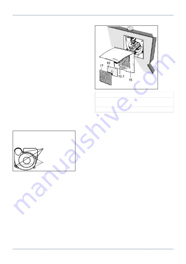
9.6 Installing the cover
15
Cover with central screw [15.1]
16
Regulating plate for second room connec-
tion
17
Filter mat, filter class G2
Installation information
• Cover can be turned up to ± 5° (to provide com-
pensation if housing is inserted at too much of
an angle). If installing on a wall, ensure that the
Maico name is in the bottom right.
• If the housing edge is flush with the plaster, use
central screw, M6 x 16 mm, to secure the
cover.
• With a plaster overshoot of up to 20 mm to the
housing edge, use spacing frame DR 60/100
between the wall and cover. The customer
should provide a longer screw (M6 fillister head)
to secure the cover.
• If the housing is plastered in too deep, com-
pensate for this with a two-part wall frame ER-
MR (can be adjusted between 50...100 mm).
This prevents air from being drawn in from the
shaft. Use the supplied screw to fix the cover.
1. Fold up cover at the recessed grip, place on
the housing and secure with the central screw.
2. If necessary, first fit a spacing or wall frame.
3. With second room extraction, insert regulating
plate below locking tabs at the side on the in-
take grille of the cover, insert filter mat.
4. Lock cover. The lock must engage audibly.
5. Switch on mains fuse, remove warning sign.
6. Undertake initial commissioning and function
test.


