


6 Mounting preparations
14
6. Cut connection duct to length, note a max-
imum duct length of 2 m.
Cut connection duct to a length which al-
lows it to be fitted on the exhaust socket
and also sealed for ventilation at the unit
end.
7. Lay suction duct and seal gap remaining cor-
rectly as described in previous installtion in-
structions.
8. Lay power cable in shaft and allow to protrude
by around 30 cm above the shaft opening.
9. In the ceiling area, fit a spigot made from shaft
material F90 around the shaft.
The spigot compensates for the length of
the shaft walls in the event of a fire.
10.Lay power cable: Provide unit with electrical
connection.
6.3 Ceiling installation preparations
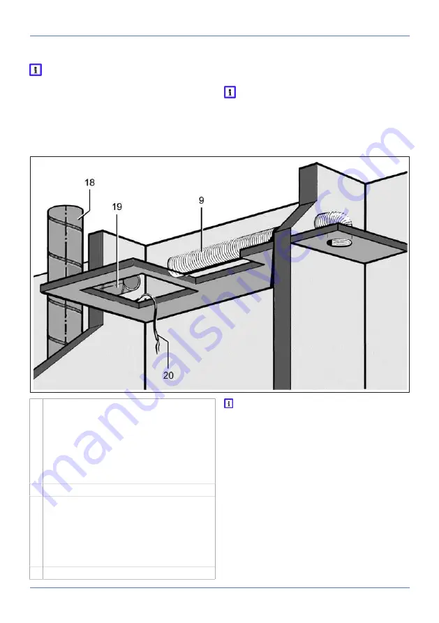
9 Suction duct for second room connection on
ER-UP/G: Flexible aluminium duct AFR 75/
AFR 80
ER-UPD: Flexible aluminium duct AFR 75/
AFR 80
or steel folded spiral-seams duct DN75/DN80
ER-UPB: Steel folded spiral-seams duct
DN75/DN80
18 Main duct: Steel folded spiral-seams duct
19 Connection duct on
ER-UP/G: Flexible aluminium duct AFR 75/
AFR 80
ER-UPD: Steel folded spiral-seams duct
DN75/DN80
ER-UPB: Steel folded spiral-seams duct
DN75/DN80
20 Power cable
Be sure to note the approval and installa-
tion information
: Preparations for wall installa-
tion.
Preparing the shaft and suspended ceiling
1. Make an opening in the suspended ceiling.
2. Make an opening in the shaft for DN 75 or DN
80 connection duct.
3. For a second room connection, produce the
opening in the wall or shaft for the suction
duct. Observe installation positions for the
second room connection.


