7 Housing installation
17
If installing on the wall with air outlet direc-
tion (exhaust socket) to the left or right, note
the following. Install shutter turned 90° (Pos.
[L] or [R]) so it closes fully sealed in the install-
ation position.
Preparing the plastic shutter for wall installa-
tion
Upwards air outlet direction "O"
Do not carry out any modifications. The shutter is
fitted correctly ex-factory.
Air outlet direction to the right "R"
1. Remove plastic backflow preventer. Simply
pull this down and out of the exhaust socket.
2. Turn backflow preventer, pos. [R].
3. Insert backflow preventer in exhaust socket
until stop is reached.
Air outlet direction to the left "L"
4. Remove plastic backflow preventer. Simply
pull this down and out of the exhaust socket.
5. Turn backflow preventer, pos. [L].
6. Insert backflow preventer in exhaust socket
until stop is reached.
Preparing the plastic shutter for ceiling install-
ation
As a rule use the standard installation position
with upwards air outlet direction "O" for ceiling in-
stallation. The shutter is fitted correctly ex-factory.
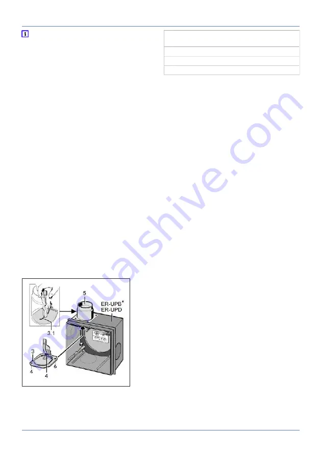
6.5.2 Fire protection shut-off device - ER-UPD
and ER-UPB housing
3 Metal shut-off shutter with release mechan-
ism and yoke spring [3.1]
4 Soldered strut
5 Metal exhaust socket
* Shown without fire protection board
NOTICE The fire protection shut-off device is
permanently closed if there is no soldered
strut.
Air extraction is then no longer possible.
Check that the soldered strut is inserted correctly
before installation. The functionality of the re-
lease mechanism must be ensured so that the
shut-off shutter also opens in normal operation.
NOTICE Unpleasant smells from the main
duct.
The fire protection shut-off device does not close
fully sealed if incorrectly installed.
Before installation, check and ensure that the in-
stallation position is correct and the release
mechanism is fully functional.
Preparing the metal shut-off device with up-
wards air outlet direction
1. Remove the fitted yoke spring. To do this, use
pliers to pull yoke spring out of exhaust socket
from above.
2. Check and ensure that shut-off shutter is fully
functional.
Preparing the metal shut-off device with air
outlet direction to the right or left
No modifications needed.
1. Check and ensure that shut-off shutter is fully
functional.
7 Housing installation
7.1 Installing ER-UP/G housing
The following are not permitted:
• Second room connection with an ER 60 fan in-
sert (all models).
• Second room connection in combination with
Centro exhaust air elements.
• Connecting a WC odour extraction unit in com-
bination with Centro exhaust elements.
• Use of an ER fan or Centro exhaust air element
in the bathroom or toilet room, if other rooms in
the apartment are to be vented with the same
unit at the same time.


