


7 Housing installation
24
9. Plaster in housing flush with front edge, note
tile thickness if necessary: Important informa-
tion about plastering.
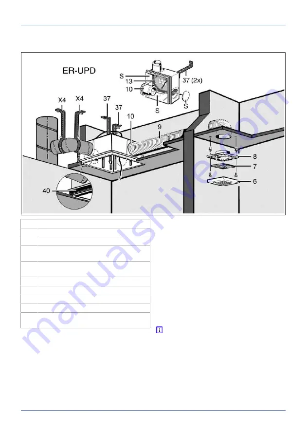
7.12 ER-UP/D installation, second
room
6
Protective grille
7
Filter mat, filter class G2
8
Adapter
9
Suction duct, second room connection:
flexible aluminium duct AFR 75/AFR 80
10
Plastic installation socket for second room
extraction DN 75/80
13
Housing floor seal
37
Mounting support UPM 60/100 (2 items)
40
ER-MO expanded rubber
S
Housing segment
X4
Clamping band or steel threaded rod with
duct clamp
1. Cut out housing segment on the marking using
a knife.
NOTICE The unit will be damaged and func-
tion impaired by incorrect air if the plastic
socket is inserted incorrectly.
Degree of protection is no longer guaranteed.
Lift up housing floor seal near socket and insert
installation socket. Reinsert housing floor seal in
the correct position.
2. Place installation socket in housing. The edge
of the socket must click into place on the wall
of the housing.
3. Install housing as described above for
single
room
.
4. Connect suction duct with installation socket
sealed for ventilation.
5. Produce fixing holes for adapter and insert
dowels.
6. Connect adapter to suction duct, e.g. with
cold-shrink tape.
7. Secure adapter to the wall.
8. Insert filter mat and locate the internal grille in
the correct position.
With second room extraction, keep regulat-
ing plate somewhere safe for the final installa-
tion. This is needed to operate the ER 100 fan
insert and is inserted in the cover.
7.13 Installation of ER-UPB housing
The following are not permitted:
• Second room connection with an ER 60 fan in-
sert (all models).


