


10 Commissioning
32
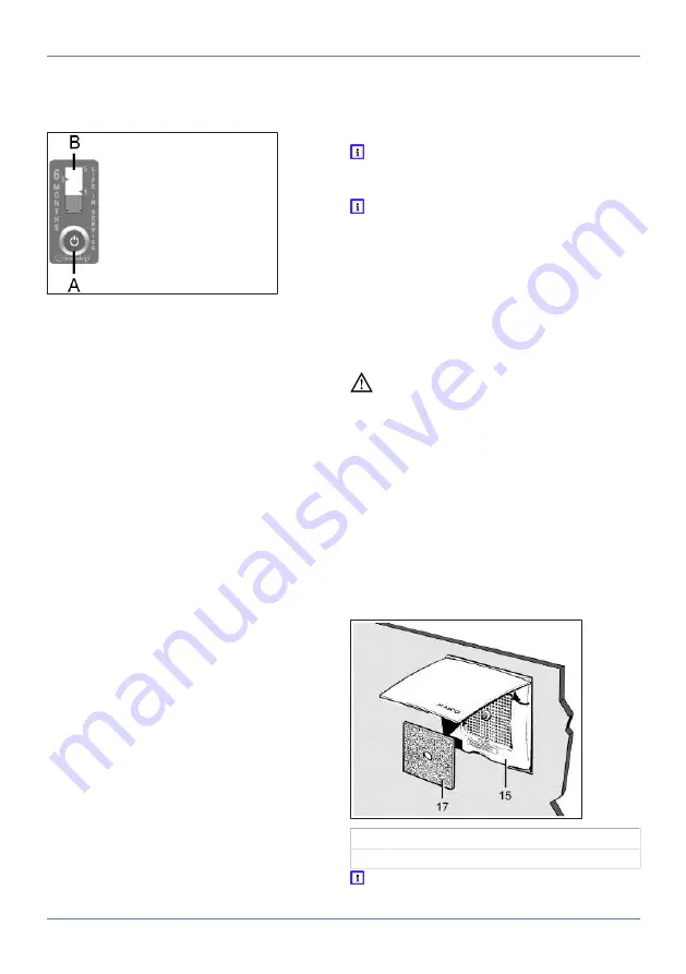
7. Affix time strip (supplied with the cover) and
push the activation button [A] all the way. In-
stallation location of time strip, e.g. near the
cover.
The red dye in the interior of the
bar [B] is released. The
bar indicator first fills
slightly. Within the
next 6 months, the bar
indicator [B] will rise to the
upper edge (indicator value 6).
10 Commissioning
1. Switch on mains fuse and remove warning
sign.
2. Run function test. To do this, switch fan on
and off, observe delay times (control models).
Take additional instructions provided into ac-
count.
3. Check that the fan is running smoothly.
4. Switch off unit.
11 Operating the unit
ER-UP/Centro units are usually switched on and
off manually (using a switch), depending on unit
model and connection variant.
Barrier-free units work as per the automatic func-
tion. Alternatively, these units can be operated
using an optional switch.
Please read the relevant sections in these instruc-
tions (
ER-UP controls (circuit board types) [
contact your installer or planner for details of the
special functions and operating characteristics.
Control model standard, D, VZ, VZC, G, GVZ, I
and RC
The unit is switched on and off with a switch that
is to be provided by the customer.
Control model F
Barrier-free unit. The fan switches on once the
room lighting is activated. The fan can also be op-
erated manually using an optional switch (
).
Control model H
Barrier-free unit. The unit switches on when the
humidity reference value Rf is exceeded. No
switch needed. The unit can also be operated
manually using an optional switch (
).
Control model RC
Radio-controlled fan system with up to 3 ER 100
RC fans. These are switched on and off via a ra-
dio switch, room air control RLS RC or radio win-
dow contacts.
If the fan is switched on and off manually,
function in accordance with DIN 18017-3 is
not always ensured.
In the event of thermal overload, the unit
switches off automatically. Wait until the mo-
tor has cooled down. Cool-down time may be
up to 10 minutes. The unit switches back on
automatically after cooling down.
12 Cleaning, maintenance
The unit is practically maintenance-free. The air
filter simply needs replacing every 3 to 6 months,
depending on the degree of soiling.
DANGER Danger to life from electric
shock.
Prior to accessing the connection terminals,
switch off all supply circuits. Switch off mains
fuse, secure against being accidentally switched
back on and position a visible warning sign.
NOTICE Risk of damage to unit if incorrect
cleaning agent is used.
Only clean the cover using water.
Do not use aggressive cleaning agents.
1. Clean housing components with dry cloth only.
2. If the cover or upper part of the housing is very
dirty, clean with water.
Filter change
15
Cover
17
Filter mat, filter class G2
Filter change interval every 3 to 6 months,
depending on the degree of soiling.


