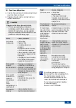
14. Installation of fan insert and cover
25
14. Installation of fan insert and
cover
14.1 Settings on electronic circuit
boards
Notes
● Electronic circuit boards [12] of the ER
variants standard EVZ, EG and EH have
no setting options.
● Electronic circuit boards [4] of the ER
variant H are equipped with an automatic
humidity function. For unit functions
chap. 7.3.3.
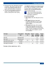
● Tolerance for time details max. + 20 %.
● Units with a time delay switch (EVZ and
EH fans) have resistance to interference in
line with EN 55014-2 (depending on pulse
form and energy factor 1000 to 4000 V).
These values can be exceeded when ope-
rating with fluorescent tubes. In this case,
additional interference suppression mea-
sures (L, C components or RC module,
protection diodes, varistors) are required.
Setting
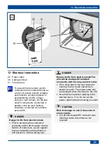
1. Place fan insert on front so that electronic
circuit board [4] (control) is freely acces-
sible.
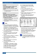
2. Set the desired values as follows with the
potentiometers or jumpers.
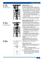
Electronic circuit boards ER 60 EH and
ER 100 EH
Humidity control function on EH units
Once the fan insert has been installed, the
unit regulates to the current room humidity
(relative humidity). This humidity value is
saved as the first reference value. The
reference value does not have to be specified
manually.
If the relative humidity
falls
below the
reference value during operation, the newly
established reference value is saved.
If the room humidity
increases
by 10 %
within 2 minutes, the fan automatically
switches to the nominal load level (60 or
100 m³/h).
If there are no further increases, the unit
continues to run at nominal load level 1 until
the humidity again falls below the saved
reference value.
If the humidity falls below the saved reference
value, the overrun operation starts with an
overrun time of 15 minutes.
If the humidity does not fall below the reference
value within 60 minutes, the unit switches back
into the operating status before the humidity
control was activated. The current humidity
value is saved as the new reference value.
ER EH units
can also be operated using the
light switch. With “Light on”, the fan starts in
nominal load. Actuation via the light switch
takes priority over the automatic humidity
function. With “Light off”, the unit continues
to run until the remaining overrun time has
passed. The automatic humidity process is
then assigned maximum priority again and
controls the unit.
14.2 Installing fan insert
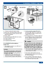
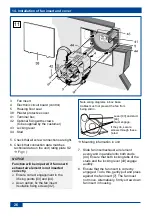
Fig. 11
The ER fan insert is inserted into the ER-
UP/GH recess-mounted housing as follows.
1. Switch off mains fuse, secure and fit
warning sign.
2. Remove plaster protective cover [38] and
clean any dirt off the recess-mounted
housing.
3. Ensure that the fan type ticked in the
housing box matches the type to be fitted.
Check ease of movement of backflow
preventer. When installed, the backflow
preventer must close automatically.
4. Check that the housing floor seal is
correctly positioned and insert properly.
NOTICE
The noise level will increase if the
housing floor seal [5] is fitted
incorrectly.
Degree of protection not guaranteed if
housing floor seal is positioned
incorrectly.
The housing floor seal must lie flat and
without any creases in the housing.
Summary of Contents for ER-UP/GH
Page 2: ...2 1...

