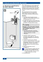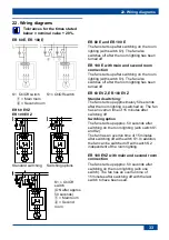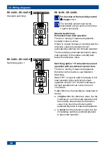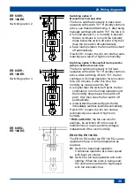
14. Installation of fan insert and cover
27
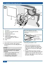
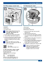
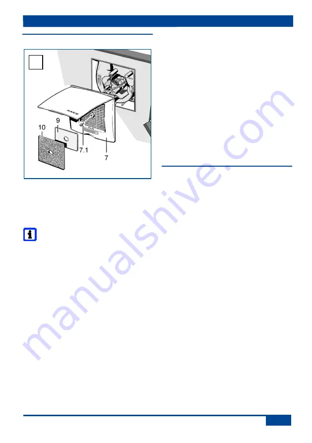
14.3 Installing the cover
7 Cover with central screw [7.1]
9 Regulating plate for second room
connection
10 Filter mat, filter class G2
Mounting information
● Cover [7] can be turned up to ± 5° (to pro-
vide compensation if housing is inserted at
too much of an angle). If installing on a
wall, ensure that the Maico name is in the
bottom right.
● If the housing edge is flush with the plas-
ter, use central screw [7.1], M6 x 16 mm,
to secure the cover.
● With a plaster overshoot of up to 20 mm
to the housing edge, use spacing frame
DR 60/100 between the wall and cover.
The customer should provide a longer
screw to secure the cover.
● If the housing is plastered in too deep,
compensate for this with a two-part wall
frame ER-MR (can be adjusted between
50...100 mm). This prevents air from being
drawn in from the shaft. Use the supplied
screw to fix the cover.
1. Fold up cover [7] at the recessed grip,
place on the ER-UP housing and secure
with the central screw [7.1].
2. If necessary, first fit a spacing or wall
frame.
3. With second room extraction, insert
regulating plate [9] below locking tabs at
the side on the intake grille of the cover,
insert filter mat [10].
4. Lock cover [7]. The lock must engage
audibly.
5. Switch on mains fuse, remove warning
sign.
6. Undertake initial commissioning and
function test.
15. Commissioning
1. Switch on mains fuse and remove warning
sign.
2. Run function test. This involves switching
the fan on and off, note delay times (for
control versions
chapter 7.3.3, ER-UP
controls). Take additional instructions
provided into account.
3. Check that the fan is running smoothly.
4. Switch off unit.
12
Summary of Contents for ER-UP/GH
Page 2: ...2 1...

