14. Installation of fan insert and cover
34
14. Installation of fan insert and
cover
14.1 Settings on electronic circuit boards
Information
●
Electronic circuit boards [12] of the ER
variants standard, D, VZ, VZ 15, G, GVZ
and F have no setting options.
●
Electronic circuit boards [12] of the ER
variants I, VZC, H, RC and GVZC can be
set as follows. For unit functions
chap. 7.4.6.
●
Tolerance for time details max. + 20 %.
●
Units with time delay switches
(VZ, VZ 15, GVZ, VZC, GVZC EC, F, I,
RC and H fans) have resistance to
interference in line with EN 55014-2
(depending on pulse form and energy
factor 1000 to 4000 V). These values
can be exceeded when operating with
fluorescent tubes. In this case, additional
interference suppression measures (L, C
components or RC module, protection
diodes, varistors) are required.
Setting
1. Place fan insert on front so that electronic
circuit board [12] (control) is freely
accessible.
2. Set the desired values as follows with the
potentiometers or jumpers.
Electronic circuit boards ER 60 I and
ER 100 I
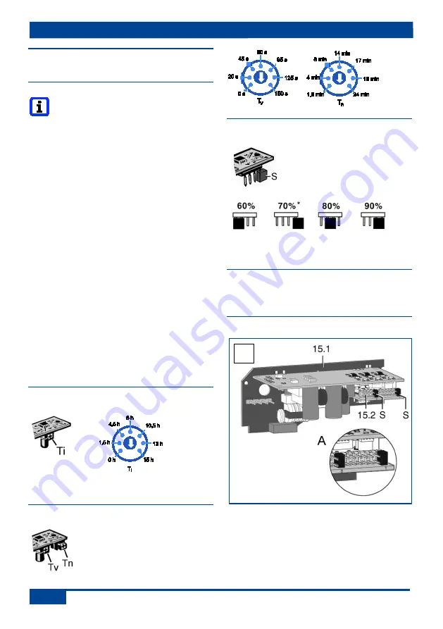
Potentiometer Ti:
Service life. In far left
position, interval control off.
Electronic circuit boards ER 60 VZC and
ER 100 VZC
Potentiometer Tv
Start delay (seconds)
Potentiometer Tn
Overrun time (minutes)
Electronic circuit boards ER 60 H and
ER 100 H
Set the humidity switch-on
point with jumper S.
*
Factory setting 70 % rel.
hum.
Only approved for second room
connection.
Electronic circuit board ER 100 RC
Separate ER 100 RC operating
instructions.
ER 60 GVZC EC
15.1 GVZC EC board
15.2 Plug connector
S
Jumper
Fig. 16 A:
Factory setting with start delay of
½ min. and overrun time of 15 min.
16


