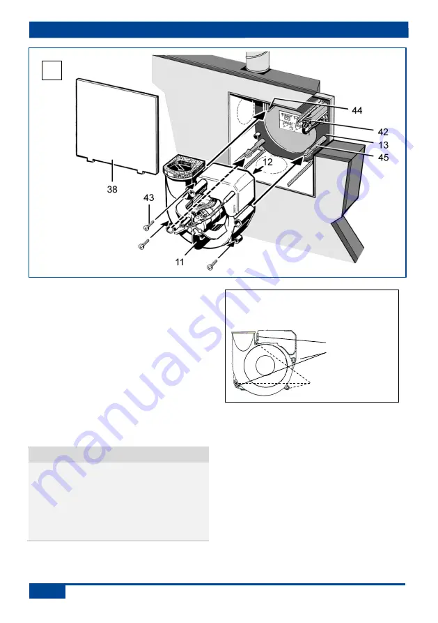
14. Installation of fan insert and cover
36
11 Fan insert
12 Electronic circuit board (control)
13 Housing floor seal
38 Plaster protective cover
42 Terminal box
43 Optional fixing with screws
(to be supplied by the customer)
44 Locking lever
45 Stud
6. Check that all screw connections are tight.
7. Check that connection data matches
technical data on the unit (rating plate
S2
Fig.1 ).
NOTICE
Function will be impaired if fan
insert/exhaust air element is not
inserted correctly.
Ensure correct engagement in the
3 fixing points [44] and [45].
As an option, fix the fan insert
3 suitable fixing screws [43].
8. Slide fan insert/exhaust air element
evenly and in parallel onto both studs
[45]. Ensure that both locking tabs of the
studs and the locking lever [44] engage
audibly.
9. Ensure that the fan insert / exhaust air
element is correctly engaged. To do this,
gently pull and press against the fan
insert / exhaust air element [11]. The
fan / exhaust air element must not move.
Alternatively, securely screw down the fan
insert/exhaust air element in the housing
previous mounting instructions.
17
Note wiring diagrams in box base.
Cables must not prevent the fan from
being slid in.
If they do, secure
screws through
these holes [43] !
Lever [44] and stud
[45] must engage.


