40
8.8 Laying ducts
The ground collectors should be laid and
commissioned in accordance with "VDI 4640"
and the associated safety fittings installed in
accordance with "DIN 4708 Central warm
water heating systems".
The ground collectors can be laid following an
individual laying plan or, more cost-
effectively, when producing the foundations.
Depending on the required heating power
and the distributor, 2 to 5 ducting branches
will be planned on one pump. As a rule in a
one-family house, 2 ducting branches with a
maximum length of 2 x 50m are sufficient,
so that the pressure loss is not too high.
Recommendation
●
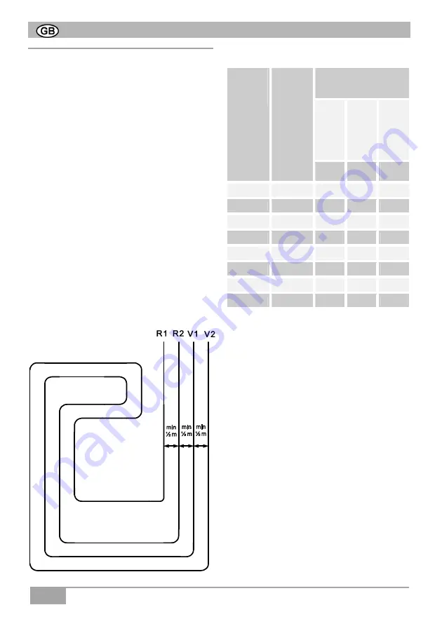
Refer to the table for configuring the layout
of the ducting.
●
Maximum length of each ducting branch
50 m. Otherwise lay a further ducting
branch.
●
Minimum spacing between the ducting
branches of 0.5 m (V = Forward flow,
R = Return flow).
Permissible ducting lengths
Air
volumetric
flow
(V)
Ground
extraction
rating (Q)
Ducting length
(2 m PE duct per m²
collector surface)
dry,
frictio
nal
soil
C
om
pact
soli,
dam
p
Wa
te
r-
satu
ra
te
d
sa
nd
/
gr
av
el
10
W/m²
20
W/m²
40
W/m²
[m³/h]
[W]
[m]
[m]
[m]
100
533
107
53
27
150
800
160
80
40
200
1067
213
107
53
250
1333
267
133
67
300
1600
320
160
80
350
1867
373
187
93
400
2133
427
213
107
As a rough estimate, you can work on the
basis of 0.5 m brine ducting per 1 m³/h air
quantity. However, a minimum of 100 m
with smaller syst
To be able to securely rule
out the possibility of damage to the ducts, the
collector ducts must be placed in a bed of
0.4 m of sand
. Furthermore advantages of
this kind of laying:
●
No air inclusions which reduce conductibility
●
The ground is able to absorb more damp-
ness
The following points must be taken into
account when laying the ducting:
●
The ground collectors must be switched in
parallel.
●
The required laying spacing must be
observed.
●
The ground collectors must be of the same
length to ensure even flows through the
circuits and so that costly regulation is not
needed on the distributor.


