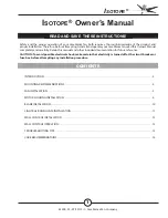
6 Vue d‘ensemble de l‘appareil Fig. A
Intérieur FE 100/1 AP/SG
1 Ventilateur ECA 100 ipro
(pas dans la fourniture)
2 Manchon fileté
3 Cadre d‘entretoise
4 Décharge de traction
5 Manchon de câble
6 Joint d‘étanchéité
Extérieur FE 100/1 AP/SG
7 Joint d‘étanchéité
8 Adaptateur
9 Moustiquaire FG 100 (pas dans
la fourniture)
10 FE 100/1 AP : Volet extérieur automatique
FE 100/1 SG : Grille extérieure fixe
S Vitre
Cadre d‘entretoise ECA-DR
Le kit comprend 3 cadres d‘entretoise [3]
7 Préparatifs de montage
AVERTISSEMENT
par électrocution au
contact de pièces sous tension. Avant
d‘accéder aux bornes, couper tous les cir-
cuits d‘alimentation électrique. Désactiver
le fusible secteur, sécuriser contre toute
remise en service intempestive et apposer
un panneau d‘avertissement de manière.
Montage en fenêtre
AVERTISSEMENT
de coupures provo-
quées par le bris d‘une vitre sous cont-
rainte.
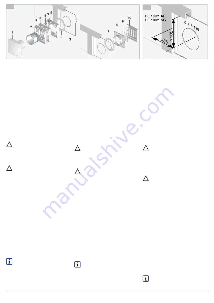
1. Faire monter une découpe de vitre Ø de 115
à 120 mm par l‘installateur spécialisé. En
cas de montage mural ou sur une plaque de
bois, percer la découpe. Diamètres/écarts
min.
Fig. B.
2. Poser le câble secteur jusqu‘au lieu d‘in-
stallation. Prévoir des lignes de longueur
suffisante pour le branchement électrique.
Montage au mur/plafond dans gaine rectan-
gulaire plate
1. Perçage de cloison de Ø 105 à 110 mm.
Pour écarts min.
Fig. C.
2. Aplanir le sol.
3. Poser le câble secteur sur le lieu d‘installati-
on. Prévoir des lignes de longueur suffisante
pour le branchement électrique.
4.
Percer des orifices des chevilles (4x S8)
pour volet extérieur/grille extérieure et cadre
d‘entretoise et introduire les chevilles. Tenir
compte de la position du passage de câble
à travers le cadre d‘entretoise.
8 Montage de la fenêtre FE 100/1 AP/SG
Sont prescrits pour le branchement élec-
trique des câbles de raccordement du type
H05 VV-F 3X 0,75 ou H05 VV-F 4G 0,75.
!
!
6 Unit overview Figure A
Inside of FE 100/1 AP/SG
1 ECA 100 ipro fan (not included in scope
of delivery)
2 Threaded connector
3 Spacing frame
4 Tension relief
5 Cable grommet
6 Gasket
Outside of FE 100/1 AP/SG
7 Gasket
8 Adapter
9 Fly screen FG 100 (not included in scope
of delivery)
10 FE 100/1 AP: Airstream-operated shutter
FE 100/1 SG: Fixed external grille
S Window pane
Spacing frame ECA-DR
Kit comprising 3 spacing frames [3]
7 Installation preparations
WARNING
from electric shock. Prior to
access to the connection terminals switch
off all supply circuits, switch off mains fuse,
secure against being accidentally swit
-
ched back on and position a warning sign.
Window installation
WARNING
of injury due to cuts caused
by glass breakage, if the windowpane is
under stress.
1.
Have trained specialist produce window cut-
out with diameter of 115 to 120 mm.
Drill cut-out in the case of wall / wooden pa
-
nel installation. Minimum diameter/spacing
Fig. B.
2.
Lay power cable to installation location.
Ensure a sufficient cable length for electrical
connection.
Wall/ceiling installation in flat channel
1.
Drill wall breakthrough with diameter of 105
to 110 mm. For minimum spacing
Fig. C.
2. Create a level base.
3.
Route suitable power cable to installation
location. Ensure a sufficient cable length for
electrical connection.
4.
Drill dowel holes (4x S8) for shutter/external
grille and spacing frames and insert dowels.
Note position of cable bushing through the
spacing frames.
8 Window installation FE 100/1 AP/SG
Flexible electrical cables, type H05 VV-F
3X 0.75 or H05 VV-F 4G 0.75, are requi
-
red for the electrical connection.
For installation preparations
Chapter 7.
1.
Select desired number of spacing frames [3]
depending on window pane thickness.
!
!
6 Geräteübersicht
Abb. A
Innenseite FE 100/1 AP/SG
1 Ventilator ECA 100 ipro
(nicht im Lieferumfang)
2 Gewindestutzen
3 Distanzrahmen
4 Zugentlastung
5 Leitungstülle
6 Dichtring
Außenseite FE 100/1 AP/SG
7 Dichtring
8 Adapter
9 Fliegengitter FG 100 (nicht im Lieferumfang)
10 FE 100/1 AP: Selbsttätige Außenklappe
FE 100/1 SG: Feststehendes Außengitter
S Scheibe
Distanzrahmen ECA-DR
Set
bestehend aus 3 Distanzrahmen [3]
7 Montagevorbereitungen
WARNUNG
vor Stromschlag. Vor Zugang
zu den Anschlussklemmen alle Versor
-
gungsstromkreise abschalten, Netzsiche
-
rung ausschalten, gegen Wiedereinschal
-
ten sichern und Warnschild anbringen.
Fenstereinbau
WARNUNG
vor Schnittverletzungen bei
Glasbruch bei unter Spannung stehender
Scheibe.
1. Scheibenausschnitt Ø 115 bis 120 mm vom
Fachinstallateur anbringen lassen.
Bei Wand-/Holzplattenmontage Ausschnitt
bohren. Mindestdurchmesser/-abstände
Abb. B.
2.
Netzleitung bis Montageort verlegen. Aus-
reichende Leitungslänge für elektrischen
Anschluss berücksichtigen.
Wand-/Deckeneinbau in Flachkanal
1.
Wanddurchbruch Ø 105 bis 110 mm bohren.
Für Mindestabstände
Abb. C.
2.
Ebenen Untergrund schaffen.
3.
Passende Netzleitung an Montageort
verlegen. Ausreichende Leitungslänge für
elektrischen Anschluss berücksichtigen.
4.
Dübellöcher (4x S8) für Außenklappe/Außen
-
gitter und Distanzrahmen bohren und Dübel
einstecken. Auf Position der Leitungsdurch
-
führung durch die Distanzrahmen achten.
8 Fenstereinbau FE 100/1 AP/SG
Für den elektrischen Anschluss vorge
-
schrieben sind flexible Anschlussleitung
vom Typ H05 VV-F 3X 0,75 oder
H05 VV-F 4G 0,75.
Für Montagevorbereitungen
Kapitel 7.
1.
Gewünschte Anzahl an Distanzrahmen [3] je
nach Scheibendicke auswählen.
!
!
A
B