


Pour les préparatifs de montage
Chapitre 7.
1. Choisir le nombre de cadres d‘entretoise [3]
selon l‘épaisseur de vitre.
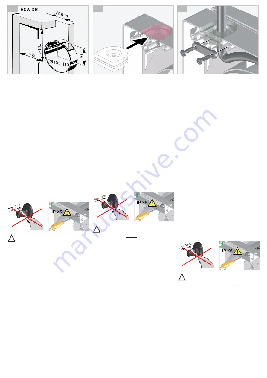
2. Sur un cadre d‘entretoise [3], découper
l‘échancrure du boîtier (partie mince) et
introduire le manchon de câble [5]
Fig. D.
3.
Enfoncer le manchon de câble [5] avec un
tournevis et introduire le câble secteur à
travers le manchon. Contrôler l‘assise du
manchon de câble.
4. Fixer le câble secteur avec la décharge de
traction et le poser dans le cadre vers la
droite
Fig. E.
5. Pousser le câble secteur à travers le trou
de 10,5 mm des autres cadres d‘entretoise
Fig. F.
6. Emboîter les cadres d‘entretoise les uns
dans les autres jusqu‘à ce que l‘enclenche-
ment soit audible.
7. Poser le joint [6] sur le cadre d‘entretoise
intérieur avec manchon de câble, joint [7]
sur les supports du volet extérieur/de la grille
extérieure.
8.
Poser le volet extérieur/la grille extérieure
sur l‘extérieur de la vitre et le bloc de cadre
d‘entretoise sur l‘intérieur de la vitre, aligner
toutes les pièces et les visser ensemble
avec le manchon fileté [2]. Les joints [6] et
[7] doivent affleurer la vitre.
9.
Enfoncer le manchon de câble ECA 100 ipro
avec un tournevis. Ne percer qu‘un petit trou
dans le manchon.
ATTENTION:
La protection IP n‘est assurée
que si le manchon de câble du ventilateur
est correctement percé. Ne pas sectionner
le manchon de câble comme décrit dans
la notice de montage du ECA 100 ipro !
10. Guider le câble secteur à travers le man-
chon de câble du ventilateur dans l‘espace
de raccordement. Le manchon de câble doit
envelopper étroitement le câble secteur pour
assurer IP X5.
11. Visser le ventilateur sur le cadre d‘entretoise
avec 2 vis
Fig. G.
12. Poursuivre le branchement et le montage
du ventilateur selon la notice de montage du
ventilateur.
!
2. Cut out the housing recess (thin point) on
one spacing frame [3] and slide in cable
grommet [5]
Fig. D.
3. Push through cable grommet [5] with
screwdriver and guide power cable through
grommet. Check position of cable grommet.
4.
Secure power cable with tension relief and
lay to the right in the frame
Fig. E.
5. Slide power cable through the 10.5 mm hole
in the other spacing frames
Fig. F.
6.
Push the spacing frames together until you
hear them engage.
7.
Place gasket [6] on inner spacing frame with
cable grommet, place gasket [7] on shutter/
external grille socket.
8.
Place shutter/external grille on outer window
side and spacing frame block on inner win-
dow side, align all parts and screw together
with threaded connector [2]. Gaskets [6]
and [7] must lie flat on the window pane.
9. Push through ECA 100 ipro cable grommet
with a screwdriver. Only produce a thin hole
in the grommet.
NOTICE:
IP protection is only guaranteed
if the fan cable grommet is correctly pus
-
hed through.
Do not
trim cable grommet
as described in the ECA 100 ipro installa-
tion instructions!
10.
Guide power cable through fan cable grom
-
met into connection area. Cable grommet
must seal cable sheathing of power cable
all the way round to ensure IP X5.
11.
Screw fan to spacing frame with 2 screws
Fig. G.
12.
Continue to connect and install fan in accor
-
dance with fan installation instructions.
!
2.
An einem Distanzrahmen [3] die Gehäuse
-
aussparung (Dünnstelle) ausschneiden und
Leitungstülle [5] einschieben
Abb. D.
3.
Leitungstülle [5] mit Schraubendreher durch
-
stechen und Netzleitung durch die Tülle
führen. Sitz der Leitungstülle kontrollieren.
4.
Netzleitung mit der Zugentlastung befestigen
und im Rahmen nach rechts verlegen
Abb. E.
5.
Netzleitung durch die 10,5 mm-Bohrung der
anderen Distanzrahmen schieben
Abb. F.
6.
Die Distanzrahmen ineinander drücken, bis
diese hörbar einrasten.
7.
Dichtungsring [6] auf inneren Distanzrahmen
mit Leitungstülle, Dichtungsring [7] auf Stut
-
zen Außenklappe/Außengitter auflegen.
8.
Außenklappe/Außengitter auf die äußere
Fensterseite und Distanzrahmenblock auf
die innere Fensterseite auflegen, alle Teile
ausrichten und mit Gewindestutzen [2] zu
-
sammenschrauben. Dichtungsringe [6] und
[7] müssen plan an der Scheibe anliegen.
9.
ECA 100 ipro-Leitungstülle mit einem
Schraubendreher durchstoßen. Dabei nur
ein dünnes Loch in der Tülle anbringen.
ACHTUNG:
IP-Schutz nur gewährleistet,
wenn die Ventilator-Leitungstülle ordnungs
-
gemäß durchstochen wird. Leitungstülle
nicht wie in der ECA 100 ipro-Montage-
anleitung beschrieben abschneiden!
10.
Netzleitung durch die Ventilator-Leitungstülle
in den Anschlussraum führen. Leitungstülle
muss den Leitungsmantel der Netzleitung
dicht umschließen, damit IP X5 sicherge
-
stellt ist.
11.
Ventilator mit 2 Schrauben an den Distanz
-
rahmen schrauben
Abb. G.
12. Mit Ventilatoranschluss und -montage ge-
mäß Ventilator-Montageanleitung fortfahren.
!
C
D
E


