


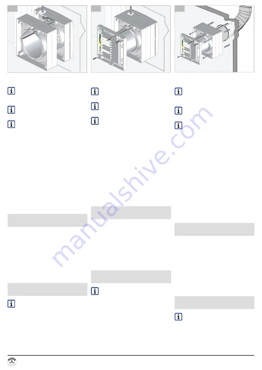
9 Montage au mur/plafond ECA-DR
dans gaine rectangulaire plate
Ne raccorder le ventilateur qu‘à une ins-
tallation électrique bien fixée. Pour câbles
autorisés
Notice de montage
du ventilateur.
Pour un montage dans une paroi de bois
ou de placoplâtre, veiller à une capacité
porteuse du mur suffisante.
Si besoin est, retirer un cadre d‘entretoise
[3] pour optimiser la profondeur d‘inserti
-
on de la bride de ventilateur dans le coude
de déviation de la gaine rectangulaire
plate. Ne retirer le cadre d‘entretoise que
si l‘épaisseur du mur suffit.
Pour les préparatifs de montage
Chapitre 7.
1. Emboîter le nombre souhaité de cadres
d‘entretoise [3] les uns dans les autres jus-
qu‘à ce que l‘enclenchement soit audible.
2. Pousser le câble secteur à travers le trou
de 10,5 mm du bloc de cadres d‘entretoise
Fig. H.
3. Fixer le bloc de cadres d‘entretoise au mur ou
au plafond avec les 4 vis longues (100 mm).
Pour ce faire, utiliser les trous Ø 5,5 mm
intérieurs.
4. Poser le manchon de câble ECA 100 ipro et
le ventilateur. Pour ce faire, procéder com
-
me au chapitre 8 (étapes 9 à 12).
Démontage / Élimination res-
pectueuse de l‘environnement
Démontage exclusivement réservé à des
électriciens qualifiés. Une élimination dans
les règles de l‘art évite les effets négatifs sur
l‘Homme et l‘environnement et permet le recy
-
clage de matières premières précieuses.
Une fois hors d‘usage, les matériaux d‘emballa
-
ge et les appareils usagés doivent être éliminés
dans le respect de l‘environnement selon les
directives locales. Les appareils usagés ne
doivent être démontés que par des spécialistes
instruits dans le domaine de l‘électricité.
Instructions de nettoyage
pour l‘utilisateur
Il est interdit de faire nettoyer l‘appareil
par des enfants ou des personnes à
capacités réduites.
● Nettoyer les pièces sales du boîtier avec un
chiffon sec.
● Tenir compte des instructions de nettoyage
du ventilateur.
9 Wall/ceiling installation of ECA-DR
in flat channel
Only connect fan to a permanent electri
-
cal installation. For permitted cables
fan installation instruction
s.
If installing in a thin wood wall or gypsum
plasterboard walls, ensure the wall has a
sufficient load-bearing capacity
.
If necessary remove one spacing frame
[3] to optimise the immersion depth of the
fan flange in the flat channel elbow. Only
remove spacing frame if the wall is thick
enough.
For installation preparations
Chapter 7.
1.
Push desired number of spacing frames [3]
together until you hear them engage.
2. Slide power cable through the 10.5 mm hole
in the spacing frame block
Fig. H.
3.
Secure spacing frame block to the wall or
ceiling with the 4 long screws supplied
(100 mm) – use the inner 5.5 mm diameter
holes.
4.
Fit ECA 100 ipro cable grommet and fan.
Continue as described in Chapter 8 (steps
9 to 12).
Dismantling / Environmentally
responsible disposal
Dismantling may only be undertaken by a trained
electrician. Professional disposal avoids detri
-
mental impact on people and the environment
and allows valuable materials to be reused.
Once they are no longer needed, packaging
materials and used units should be disposed
of in compliance with local regulations. Used
units may only be dismantled by a person with
electrical training.
Cleaning information for
the user
Do not allow children or handicapped
people to clean the unit.
● If dirty, clean the housing parts with a dry
cloth.
● Note the cleaning information for the fan.
9 Wand-/Deckenmontage ECA-DR
in Flachkanal
Ventilator nur an einer fest verlegten
elektrischen Installation anschließen.
Für zulässige Leitungen
Ventilator-
Montageanleitung.
Bei Einbau in dünne Holz- oder Gipskar
-
tonwand für ausreichende Tragfähigkeit
der Wand sorgen.
Bei Bedarf einen Distanzrahmen [3] entfer
-
nen, um die Eintauchtiefe des Ventilator
-
flansches in das Flachkanal-Winkelstück
zu optimieren. Distanzrahmen nur dann
entfernen, wenn die Wandstärke ausreicht.
Für Montagevorbereitungen
Kapitel 7.
1.
Gewünschte Anzahl an Distanzrahmen
[3] ineinander drücken, bis diese hörbar
einrasten.
2.
Netzleitung durch die 10,5 mm-Bohrung des
Distanzrahmenblocks schieben
Abb. H.
3.
Distanzrahmenblock mit den 4 mitgelieferten
langen Schrauben (100 mm) an der Wand
oder Decke befestigen – dazu die inneren
Ø 5,5 mm Löcher verwenden.
4.
ECA 100 ipro-Leitungstülle und den Ven
-
tilator anbringen. Dazu wie in Kapitel 8
beschrieben (Schritt 9 bis 12) fortfahren.
Demontage /
Umweltgerechte Entsorgung
Demontage nur durch Elektrofachkraft zulässig.
Eine fachgerechte Entsorgung vermeidet nega
-
tive Auswirkungen auf Mensch und Umwelt und
ermöglicht eine Wiederverwendung wertvoller
Rohstoffe.
Verpackungsmaterialien und Altgeräte sind
nach deren Nutzungsende umweltgerecht ge
-
mäß den örtlichen Bestimmungen zu entsorgen.
Altgeräte dürfen nur durch eine elektrotechnisch
unterwiesene Fachkraft demontiert werden.
Reinigungshinweise für
den Benutzer
Reinigung nicht durch Kinder oder Per
-
sonen mit eingeschränkten Fähigkeiten
zulässig.
● Bei Verschmutzung die Gehäuseteile mit
einem trockenen Tuch reinigen.
● Reinigungshinweise des Ventilators beach
-
ten.
Maico Elektroapparate-Fabrik GmbH • Steinbeisstr. 20 • 78056 Villingen-Schwenningen • Germany •
S49 7720 694 447 • technik@maico.de
0185.
118
0.0000_02.15_DSW
ES_02.15
F
G
H


