background image


14

6. Essential safety instructions 

General safety instructions 

●  Read the operating instructions through 

carefully before starting up. 

●  Keep the instructions. 
● 

Installation is only permitted when 
carried out by trained specialists. 

● 

Electrical connections and repairs are 
only permitted when carried out by 
trained specialists. 

●  Only use fitters and electricians who are 

sure-footed and comfortable working at 
height. 

●  The unit must not be used as a toy. 
●  Only connect the unit to a permanent 

electrical installation.  
– Permitted cable cross section: 1.5 mm². 
– Use a flexible connection cable. 
– Mains isolation device required with 
openings of at least 3 mm at each pole. 
- Use a 6-core, shielded control cable. 

●  The unit may only be operated using the 

voltage and frequency shown on the rating 
plate. 

●  Only operate the unit when it is completely 

installed.  

●  Modifications and alterations to the unit are 

not permitted and release MAICO from any 
guarantee obligations and liability. 

●  Ensure that foreign bodies cannot be 

sucked into the unit and duct. 

●  Never operate without protective grille with 

free inlet. 


Intended use 

●  For 

central air extraction

, with volumetric 

flows that differ in each apartment (Centro 
System).


●  Also for 

air extraction

 in restaurants, 

machinery rooms, workshops, 
manufacturing areas, industrial buildings, 
etc. 

●  For installation on roof socket (for flat, 

sloping, corrugated or trapezoidal roofs). 

●  Should only be installed in a horizontal 

position. It must be ensured that the 
shutters can function correctly. 


Predictable misuses 

The unit should not be used: 
●  Close to flammable materials, liquids or 

gasses. 

●  In explosive atmospheres. 
 

Safe and correct practices during 
operation 

● 

Danger of injury.

 Do not insert any objects 

in the air channel or the unit.  

● 

In the case of installation with free inlet: 
danger from rotating impeller.


Do not get too close to the unit, to avoid 
hair, clothing or jewellery being drawn into 
the unit. Use a Maico SG protective grille, 
for example. 


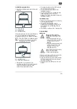
7. Transport and storage 

Transport 

●  Make sure that the GRD unit is not 

damaged, tipped or knocked over during 
transport. 

●  Only lift the GRD unit at the two fixed ring 

nuts, using suitable lifting gear, e.g. a load 
hook.  

●  Observe the slewing point (central). 
●  The permitted maximum load for lifting 

gear, chains, ropes, etc. must be sufficient 
for the transport weight (see Chapter 4). 

●  Do not stand under a suspended load 

during transportation. 


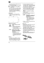
8. Installation preparation 

Requirements at installation site 

●  Observe the permissible roof load. 
●  Only screw the GRD onto a suitable roof 

socket, in order to prevent leaks. 

●  Use only roof sockets from the current 

Maico main catalogue. 


GB 

Summary of Contents for GRD 22

Page 1: ...Montage und Betriebsanleitung Dachventilator mit Regelung Mounting and operating instructions Roof fan with control unit GRD 22 GRD 25 GRD 31 www maico ventilatoren com VENTILATOREN DE EN...

Page 2: ......

Page 3: ......

Page 4: ......

Page 5: ...A B...

Page 6: ...RD Dachventilator mit Regelung Druck Anschlussset und Betriebsanleitung 2 Verwendete Warnsymbole Warnsymbole GEFAHR Lebensgefahr Eine Nichtbeachtung kann zum Tod oder zu schweren K rperverletzungen f...

Page 7: ...s Ger t an die Betriebsparameter anpassen GRD Ger te lassen sich mit Reparatur schalter 7 direkt vor Ort vom Stromnetz trennen zum Beispiel zum Reinigen Nach dem Abnehmen des Daches 1 muss der abschli...

Page 8: ...rikationsst tten Industriehallen etc Zum Aufbau auf Dachsockel f r Flach Schr g Well oder Trapezd cher Nur f r die horizontale Installation Die Funktion der Verschlussklappen muss gew hrleistet sein V...

Page 9: ...tung Querschnitt 0 25 bis 0 34 mm fest verlegen Tipps f r die Installation Planungsunterlagen des Planungsb ros ber cksichtigen Im Bereich zwischen Dachverwahrung 13 und Dachsockel geeignetes Isolatio...

Page 10: ...ehe Schaltbild auf Seite 12 Schirmgeflecht der Steuerleitung W2 an Erdungsklemme im Anschlusskasten anschlie en Feindrahtiges Schirmgeflecht nur mit Aderendh lse anschlie en Netzleitung an der Anschlu...

Page 11: ...s Men oder CPs Men SETUP immer komplett durchf hren Dr cken Sie gegebenenfalls so oft ENTER bis wieder die Betriebsanzeige erscheint Dr cken von SETUP beendet direkt das Einstellmen Die Betriebsanzeig...

Page 12: ...s Am Ende der Parameter Einstellung immer die Geh useabdeckung aufsetzen und verschrauben 11 Instandhaltung GRD Ger te sind wartungsfrei 12 Reinigung GEFAHR Lebensgefahr Ger t steht unter Spannung Ge...

Page 13: ...zur St rungsbeseitigung anzuzeigen Alarmmeldung Ma nahme VENT ALARM Funktionsst rung am Ventilator Pr fen Sie die Verdrah tung die Verbindungs leitungen und den Netzanschluss DRUCK ALARM Zu hoher Dru...

Page 14: ...r cken bis die Alarmanzeige erlischt Die Regelung arbeitet nun wie eingestellt jedoch ohne Druck Alarm Soll ein Druck Alarm eingestellt werden Fehlerursache ermitteln und beseitigen zu hoher Systemdru...

Page 15: ...n L ftungssystem umbauen Tab 5 St rungsbehebung 14 Im Reparaturfall GEFAHR Lebensgefahr Ger t steht unter Spannung GRD Ger t vom Netz trennen Dazu Dach 1 entfernen GRD Ger t mit Reparatur schalter aus...

Page 16: ...re connection kit operating instructions 2 Warning symbols used Warning symbols DANGER Danger to life Non observance can lead to death or serious bodily injuries CAUTION Danger of injury Non observanc...

Page 17: ...d adjust the unit to the operating parameters GRD units can be separated locally from the mains using the service switch 7 for cleaning purposes for example After removing the unit roof 1 the lockable...

Page 18: ...xtraction in restaurants machinery rooms workshops manufacturing areas industrial buildings etc For installation on roof socket for flat sloping corrugated or trapezoidal roofs Should only be installe...

Page 19: ...er 0 25 to 0 34 mm between the GRD unit and the control unit installation location Installation tips Observe the planning documents drawn up by the engineering office Use appropriate insulation sound...

Page 20: ...gram on Page 12 Connect the shielding braid from the control cable W2 to the grounding terminal in the terminal box Use cable end sleeves to connect the fine shielding braid Connect the power cable to...

Page 21: ...e setting Always carry out SETUP completely If necessary press ENTER as many times as is necessary until the operating display appears again Pressing SETUP quits the Setup menu directly The operating...

Page 22: ...lways replace the housing cover and screw it in place at the end of the parameter setting process 11 Maintenance GRD units require no maintenance 12 Cleaning DANGER Danger to life Unit is powered up D...

Page 23: ...ut fault rectification Alarm message Countermeasure FAN ALARM Malfunction at the fan Check wiring connection cables and mains power connection PRESS ALARM Pressure is too high in the air channel Alarm...

Page 24: ...splay goes out The control unit now works as per its settings but without pressure alarm If a pressure alarm should be set up troubleshoot the cause of the fault and eliminate it e g system pressure o...

Page 25: ...on system Tab 5 Fault rectification 14 In the case of a repair DANGER Danger to life Unit is powered up Disconnect the GRD unit completely from the mains power supply To do this remove the unit roof 1...

Page 26: ...22 GB 17 Schaltbild Wiring diagram D...

Page 27: ...23...

Page 28: ...24 Maico Elektroapparate Fabrik GmbH Steinbeisstr 20 78056 Villingen Schwenningen Germany Service 49 7720 6940 technik maico de 0185 1113 0004_RLF 2_07 18_DSW AS 07 18_Es...

Reviews: