background image

Operation Manual MA 1  


8100216 Rev. 5 

21 

09/03/2023 


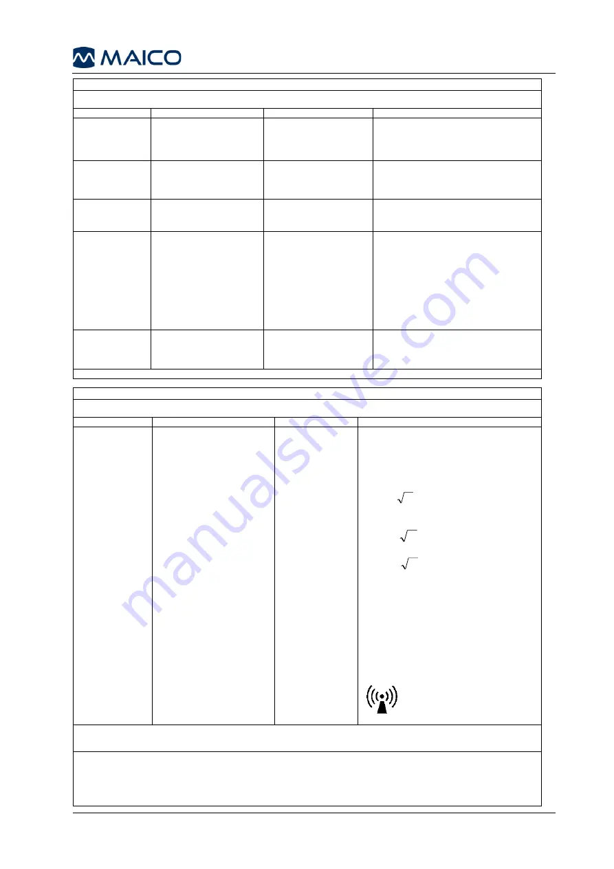
Guidance and Manufacturer’s Declaration - Electromagnetic Immunity 

The 

MA 1 

is intended for use in the electromagnetic environment specified below. The customer or the user of the 

MA 1 

should 

assure that it is used in such an environment. 

Immunity Test 

IEC 60601 Test level 

Compliance 

Electromagnetic environment - guidance 

Electrostatic 
Discharge (ESD) 
 
IEC 61000-4-2


+8 kV contact 
 
+15 kV air 

+8 kV contact 
 
+15 kV air 

Floors should be wood, concrete or ceramic 
tile. If floors are covered with synthetic 
material, the relative humidity should be 
greater than 30%. 

Electrical fast 
transient/burst  
 
IEC61000-4-4


+2 kV for power supply lines 
 
+1 kV for input/output lines


Not applicable 
 
+1 kV for input/output lines 

Mains power quality should be that of a 
typical commercial or residential environment. 

Surge 
 
IEC 61000-4-5


+1 kV differential mode 
 
+2 kV common mode 

Not applicable 

Mains power quality should be that of a 
typical commercial or residential environment.


Voltage dips, short 
interruptions and 
voltage variations 
on power supply 
lines  
 
IEC 61000-4-11 


< 5% 

U

T (>95% dip in 

U

T) 

for 0.5 cycle 
 
40% 

U

T (60% dip in 

U

T) 

for 5 cycles 
 
70% 

U

T (30% dip in 

U

T) 

for 25 cycles 
 
<5% 

U

T (>95% dip in 

U

T) 

for 5 sec


Not applicable 


Mains power quality should be that of a 
typical commercial or residential environment. 
If the user of the 

MA 1 

requires continued 

operation during power mains interruptions, it 
is recommended that the 

MA 1 

be powered 

from an uninterruptable power supply or its 
battery. 


Power frequency 
(50/60 Hz) 
 
IEC 61000-4-8


30 A/m


30 A/m


Power frequency magnetic fields should be at 
levels characteristic of a typical location in a 
typical commercial or residential environment.


Note: U

T is the A.C. mains voltage prior to application of the test level. 


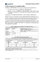
Guidance and manufacturer’s declaration — electromagnetic immunity 

The 

MA 1 

is intended for use in the electromagnetic environment specified below. The customer or the user of the 

MA 1 

 should 

assure that it is used in such an environment, 

Immunity test 

IEC / EN 60601 test level 

Compliance level 

Electromagnetic environment 

– guidance 


Portable and mobile RF communications 
equipment should be used no closer to any parts 
of the 

MA 1,

 including cables, than the 

recommended separation distance calculated 
from the equation applicable to the frequency of 
the transmitter. 

Recommended separation distance: 

Conducted RF 

3 Vrms 

3 Vrms 

P

d

2

,

1

=


IEC / EN 61000-4-6 

150kHz to 80 MHz 


Radiated RF 

3 V/m 

3 V/m 

P

d

2

,

1

=

    80 MHz to 800 MHz 

IEC / EN 61000-4-3 

80 MHz to 2,7 GHz 


P

d

3

,

2

=

   800 MHz to 2,7 GHz 


Where 

P

 is the maximum output power rating of the 

transmitter in watts (W) according to the transmitter 
manufacturer and 

d

 is the recommended separation 

distance in meters (m). 
 
Field strengths from fixed RF transmitters, as determined 
by an electromagnetic site survey,

a

 should be less than 

the compliance level in each frequency range.

b


Interference may occur in the vicinity of equipment 
marked with the following symbol: 


NOTE1 At 80 MHz and 800 MHz, the higher frequency range applies 
NOTE 2 These guidelines may not apply in all situations. Electromagnetic propagation is affected by absorption and reflection from 
structures, objects and people. 

a)


Field strengths from fixed transmitters, such as base stations for radio (cellular/cordless) telephones and land mobile radios, amateur radio, AM 

and FM radio broadcast and TV broadcast cannot be predicted theoretically with accuracy. To assess the electromagnetic environment due to 
fixed RF transmitters, an electromagnetic site survey should be considered. If the measured field strength in the location in which the 

MA 1 

is used 

exceeds the applicable RF compliance level above, the 

MA 1 

should be observed to verify normal operation, If abnormal performance is observed, 

additional measures may be necessary, such as reorienting or relocating the 

MA 1.


b)


Over the frequency range 150 kHz to 80 MHz, field strengths should be less than 3 V/m. 

Summary of Contents for MA 1

Page 1: ...Operation Manual MA 1...

Page 2: ......

Page 3: ...ng and Disinfection Recommendations 8 3 4 Disposables 9 3 5 Components Replacement Parts 9 3 6 Recycling and Disposal 9 4 Unpacking and Installation 10 4 1 Unpacking the System 10 4 2 Hardware Orienta...

Page 4: ...www maico diagnostics com german support resources International https www maico diagnostics com support resources Copyright 2023 MAICO Diagnostics All rights reserved No part of this publication may...

Page 5: ...ENTs hearing healthcare professionals or other trained technicians in a hospital clinic or healthcare facility 1 3 Contraindications of Use The patient is too young sick or uncooperative to perform th...

Page 6: ...ystem including safety information as well as maintenance and cleaning recommendations READ THIS ENTIRE OPERATION MANUAL BEFORE ATTEMPTING TO USE THIS SYSTEM Use this device only as described in this...

Page 7: ...is manual accompanying labels and or inserts A defective product should not be used Make sure all connections to external accessories are snug and secured properly Parts which may be broken or missing...

Page 8: ...tion consult accompanying documents Warning consult accompanying documents Return to authorized representative special disposal required Reference number Medical Device Global Trade Item Number Patien...

Page 9: ...calibration Do not use the device if any damage is suspected Calibration of the device The device and the transducers complement each other and share the same serial number i e MA7663252 Therefore the...

Page 10: ...device adjacent to or stacked with other equipment should be avoided because it could result in improper operation If such use is necessary this device and the other equipment should be observed to v...

Page 11: ...t of repair during the guarantee period please enclose evidence of purchase with the device 3 2 Maintenance In order to ensure that the device works properly it has to be checked and calibrated at lea...

Page 12: ...lies that are supplied with your device Ear cushion covers are intended for single use only These should be discarded after use They cannot be cleaned In case of re use of the single use disposables y...

Page 13: ...onent appears to be damaged in shipment contact your distributor immediately to report it Do not attempt to use any component or device that appears to be damaged Reporting Imperfections Notify the ca...

Page 14: ...iometric Headset 2x AA Batteries Carrying Case Operation Manual Quick Guide Audiogram Pad Applied parts according to IEC 60601 1 As download from the download center see accompanying leaflet Table 3 R...

Page 15: ...attery life The device will power off after 90 s of inactivity When batteries get too low to produce the proper signal remaining battery power of 2 1 V or lower the device will shut off and will not t...

Page 16: ...condensation by storing the device in its original packaging If the device is stored under warmer conditions than the use conditions no special precaution are required before use Always ensure proper...

Page 17: ...r Conduction Testing 5 4 1 Screening A hearing screening utilizes a Pass or Refer result and is used to determine if further testing is required as a hearing problem may exist Patients are typically s...

Page 18: ...ither ear would result in a Refer Note When presenting tones be sure to vary the timing of the tone presentation This is to prevent the patient from routinely raising his her hand instead of respondin...

Page 19: ...e disposal of authorized service companies STANDARDS Safety Standards IEC 60601 1 2005 Cor 2006 Cor 2007 A1 2012 Internally powered Type B Applied Parts EMC Standard IEC 60601 1 2 2014 The MA 1 is not...

Page 20: ...ansducers Headband tension DD45 Headband Static Force 4 5 N 0 5 N DD65 v2 Headband Static Force 10 0 N 0 7 N Inputs Tone Accuracy Level 4 dB Precision 5 dB level steps Outputs Left Right Stimuli Prese...

Page 21: ...al MA 1 8100216 Rev 5 18 09 03 2023 6 2 Connections Figure 5 CONNECTIONS No Connection socket Specification 1 Phone ZA 10 UA 7 Veff 6 3 Pin Assignment SOCKET CONNECTOR PIN 1 PIN 2 Phone 3 5 mm Mono Gr...

Page 22: ...lent threshold sound pressure level RETSPL dB re 20 Pa DD45 DD65 v2 500 7 0 26 1 1000 15 0 32 4 2000 26 0 43 6 4000 32 0 43 8 Table 7 Reference Values for Stimulus Calibration REFERENCE VALUES FOR STI...

Page 23: ...o cause any interference in nearby electronic equipment RF emissions CISPR 11 Class B The MA 1 is suitable for use in all commercial industrial business and residential environments Harmonic emissions...

Page 24: ...the electromagnetic environment specified below The customer or the user of the MA 1 should assure that it is used in such an environment Immunity test IEC EN 60601 test level Compliance level Electr...

Page 25: ...equirements for Basic Safety and Essential Performance Collateral Standard Electromagnetic Compatibility Requirements and tests 3 DIN EN ISO 14971 2012 Application of risk management to medical device...

Page 26: ...Operation Manual MA 1 8100216 Rev 5 23 09 03 2023 6 7 Checklist for Subjective Device Check...

Page 27: ...ecifications are subject to change without notice MAICO Diagnostics GmbH Sickingenstr 70 71 10553 Berlin Germany Tel 49 30 70 71 46 50 Fax 49 30 70 71 46 99 E mail sales maico biz Internet www maico b...

Reviews: