background image


4

6. Installation, Electrical connection 


DANGER 

Danger to life from electrical 
shock! 


Switch power off. ! 


 Unscrew both screws from the housing 

cover and remove the cover. 

 Make holes in the breakout points in the 

lower part of the housing, corresponding to 
the number of cables and insert grommets. 

 Fix the lower part of the housing to the wall 

using fixing material provided by the 
customer. 

 Feed the connection cables through the 

grommets. 


CAUTION 

Danger of short-circuit and 
damage to the device, caused 
by the penetration of water or 
damp ! 

 Position the grommets such 

that they fit tightly round the 
cables. 


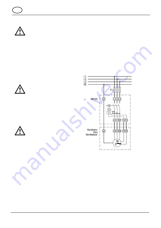
 Wire up the motor protection switch 

according to the wiring diagram. 


CAUTION 

A wrong connection will 
damage the thermal contact ! 

 Only contact the thermal 

contact to the connector 
labelled “TK”. 


 Replace the housing cover and screw it 

back down using both screws. 

 Switch the main fuse on. 

 Carry out a function test. 


7. Maintenance 

 The device is maintenance-free.  

8. Fault rectification 

 An auto-restart block prevents the motor 

switching itself back on after the motor 
winding has cooled down. 

 If switched back on too soon (within 1 

minute), the protection switch is re-
triggered. 


 Press button “0” and then button “1” to 

switch back on. 


9. Wiring diagram 


GB 

Summary of Contents for MV25

Page 1: ...rgung Bemessungsspannung 400 V Maximalbelastung 25 A Netzfrequenz 50 Hz oder 60 Hz Schutzart MV 25 IP 54 3 Umgebungsbedingungen und Grenzen f r Betrieb Zul ssige Umgebungstemperatur 40 C 4 Grundlegend...

Page 2: ...h digung durch eindringendes Wasser oder Feuchtigkeit T llen so einsetzen dass diese die Leitungen dicht umschlie en Motorvollschutzschalter gem Schaltbild verdrahten VORSICHT Besch digung der Thermo...

Page 3: ...ion MV 25 IP 54 3 Environmental conditions and operational limits Permitted ambient temperature 40 C 4 Basic safety instructions General notes regarding safety Retain instructions Installation electri...

Page 4: ...f water or damp Position the grommets such that they fit tightly round the cables Wire up the motor protection switch according to the wiring diagram CAUTION A wrong connection will damage the thermal...

Page 5: ...5 IP 54 3 Conditions environnementales et limites d utilisation Temp rature ambiante admissible 40 C 4 Consignes de s curit fondamentales Consignes de s curit g n rales Conserver le manuel Montage bra...

Page 6: ...ixer les manchons de sorte qu ils enserrent fermement les conduites C bler le disjoncteur protecteur int gral conform ment au sch ma de branchement ATTENTION Endommagement des thermo contacts en cas d...

Page 7: ...7...

Page 8: ...8 Maico Elektroapparate Fabrik GmbH Steinbeisstr 20 78056 Villingen Schwenningen Germany Service 49 7720 694 447 technik maico de DSW _ 11 03 _ 4 00 0 2 2 8 5 0 018 s 11_E 03...

Reviews: