– Subject to change ! –
5
Assembly and commissioning
•
Assembly and commissioning may be carried out
only by skilled electricians trained in explosion
protection.
•
The device may not be disassembled. The
temporary removal of the cover during the
installation of the device is not subject to this
limitation.
•
Connection of mains power and motor
Open the housing by loosening the two screw
plugs on the cover.
Install the two M 20x1.5 cable glands supplied, at
the corresponding locations in the lower part of the
housing (Fig. 1).
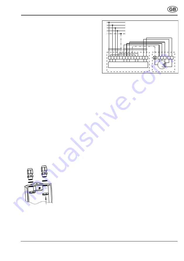
Connect the power and the motor as shown in the
wiring diagram (Fig. 2). You will find the wiring
diagram on the inside of the housing cover.
Use a shared non-metallic-sheathed cable for the
motor voltage and the PTC thermistor connection.
The thermistor triggering system may only be
used when the cover and the cable glands are in
place.
Data relating to the cable glands and housing-
cover screws:
– M 20 x 1.5 cable glands:
Torque: connection thread 4.0 Nm, pressing
screw 3.0 Nm.
Terminal size: 6 mm - 13 mm
– Housing-cover screws:
Torque 1.3 Nm
Figure 1:
Cable gland installation
Figure 2:
Wiring diagram
Maintenance and troubleshooting
•
Before starting maintenance work, the PTC
thermistor triggering device must be completely
separated from mains to prevent danger caused
by live parts.
•
Operation with malfunctions
If malfunctions occur, completely disconnect the
PTC thermistor triggering device from the mains.
Before switching it on again, have professionals
determine and eliminate the cause of the error.
•
Repairs
The PTC thermistor triggering device may be
repaired only by professionals trained in explosion
protection. Send the device back to the factory for
all repairs.
Disposal
The PTC thermistor triggering device contains some
recyclable materials and some substances that
should not be disposed of in the rubbish. After its
lifetime has elapsed, dispose the device according
to the valid regulations.
M
3
1 2 3 N P E 6 7 8 P E 1 0
1 3 1 4
N P E
P E
L 1
L 2
L 3
N
1 2 3
5 6
0074.0266.0000
M V S 6
M o t o r
Summary of Contents for MVS 6
Page 8: ......
Page 9: ......
Page 10: ...2014 34 EU 2014 34 EU Devolen teplota okol viz typov t tek...
Page 54: ......
Page 55: ......


