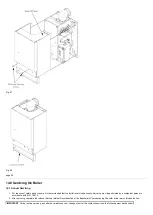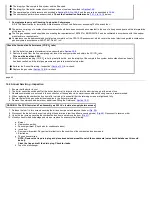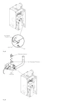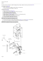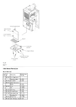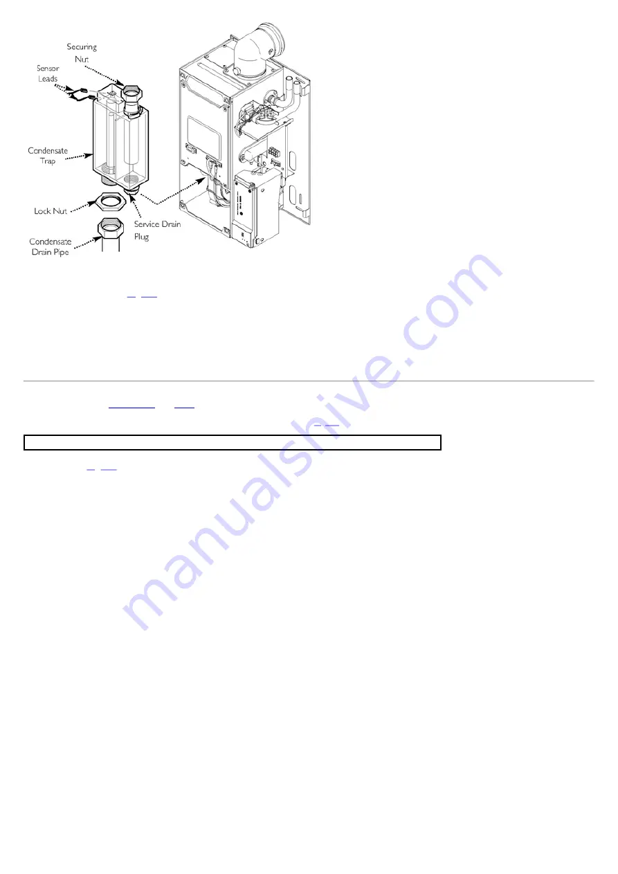
Fig. 54
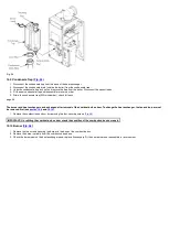
15.9 Condensate Trap (
1. Disconnect the condensate trap from the base of the heat exchanger.
2. Disconnect the condensate drain (outside the boiler) from the condensate trap.
3. Undo the condensate trap lock nut and remove the trap from the boiler. Disconnect the sensor leads.
4. Fit the new condensate trap and reassemble in reverse order.
5. Prime the condensate trap (fill first chamber), check for leaks.
page 49
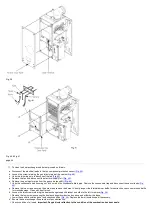
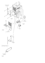
The burner and heat exchanger can be changed after removal of the combustion box door. To change the heat exchanger, the fan and burner must
be removed first (see
and
).
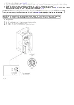
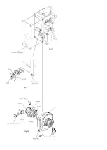
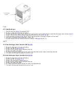
1. Remove the combustion box door by removing the four securing screws (
).
IMPORTANT: On refitting the combustion box door check the condition of the combustion box door seals.
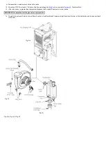
1. Remove the two screws securing the burner to the base of the combustion box.
2. Remove the burner carefully from the combustion box base.
3. Check the burner seal on the heat exchanger base, replace if necessary. Fit the new burner and reassemble in reverse order.
Summary of Contents for Main Heat 12
Page 8: ...Fig 3 Fig 4 Fig 5 Fig 6...
Page 38: ...Example 1 Example 2 Example 3...
Page 40: ...Fig E Fig F...
Page 51: ...Fig 31 Fig 32 Fig 33...
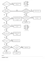
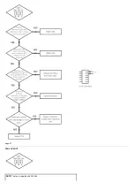
Page 55: ...Fig 35 Fig 36 page 39 12 2 Checking the Combustion 1 Follow the flow chart opposite...
Page 56: ......
Page 63: ...Fig 45 Fig 46...
Page 66: ......
Page 69: ...Fig 55 Fig 56 Fig 57 Fig 58...
Page 72: ...page 52...
Page 74: ...page 54...
Page 75: ...DRY FIRE...
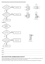
Page 76: ...page 55 IGNITION LOCKOUT...
Page 77: ...page 56 OVERHEAT LOCKOUT...
Page 78: ...page 57 FAN LOCKOUT NOTE The fan is supplied with 325 Vdc...
Page 80: ...warranty This does not affect the customer s statutory rights page 62...
Page 82: ...page 63...

