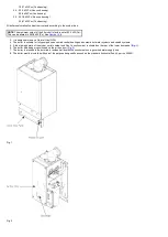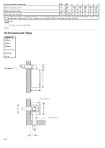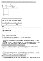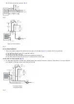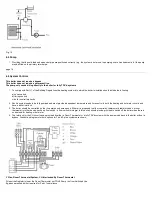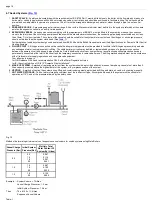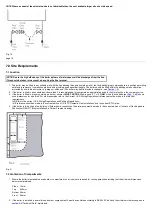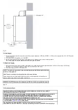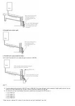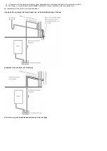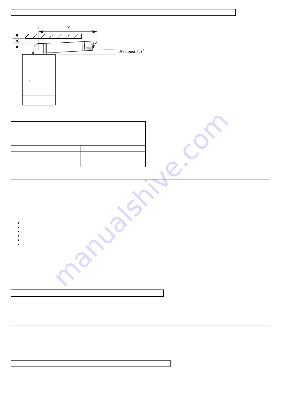
The 1.5° fall provided by the elbow is to allow condensate to run back to the boiler, for disposal through the condensate discharge pipe.
Fig. 8
SIDE FLUE (left and right)
For every 1m of horizontal flue length, the clearance above the top of the flue
elbow should be 27.5mm to incorporate the 1.5° fall in the flue from the terminal
to the elbow.
Flue length (Y)
Clearance (X)
up to 1m
1m - 2m
2m - 3m
27.5mm
55mm
82.5mm
page 12
6.0 System Details
6.1 Water Circulating Systems
1. The appliance is suitable for use with open vent fully pumped systems and sealed systems.
The following conditions should be observed on all systems:
The static head must not exceed 30m of water.
The boiler must not be used with a direct cylinder.
Drain cocks should be fitted to all system low points.
All gas and water pipes and electrical wiring must be installed in a way which would not restrict the servicing of the boiler.
Position isolating valves as close to circulating pump as possible.
It is recommended that the return pipe is fitted with an automatic air vent as close to the boiler as is practical.
6.2 Treatment of Water Circulating Systems
1. All recirculatory water systems will be subject to corrosion unless they are flushed and an appropriate water treatment is applied. To prevent this,
follow the guidelines given in BS 7593 "Treatment of Water in Domestic Hot Water Central Heating Systems"
and the treatment manufacturers
instructions.
2. Treatment must involve the use of a proprietary cleanser, such as Sentinel X300 or X400, or Fernox F3 and an inhibitor such as Sentinel X100 or
Fernox MB-1.
3. Full instructions are supplied with the products, for further information contact Sentinel (0800 389 4670) or Fernox (0870 870 0362).
Failure to flush and add inhibitor to the system will invalidate the appliance warranty.
4. It is important to check the inhibitor concentration after installation, system modification and at every service in accordance with the inhibitor
manufacturer's instructions. (Test kits are available from inhibitor stockists.)
5. For information or advice regarding any of the above contact Technical Enquiries 0844 871 1555.
page 13
6.3 Pipework
1. The sizes of flow and return pipes from the boiler should be determined by normal methods, according to the requirements of the system. The
connections on the boiler are 22mm.
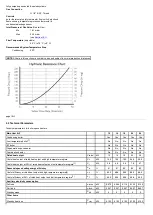
2. A 20°C drop in temperature across the system is recommended for condensing boilers. Existing radiators may be oversized and so allow this, but
where radiator sizing is marginal it may be advisable to retain a system temperature drop of 11°C.
NOTE: On 30 models 28mm pipe should be used to connect to the boiler flow and return.
3. In systems using non-metallic pipework it is necessary to use copper pipe for the boiler Flow and Return. The copper must extend at least 1 metre
Summary of Contents for Main Heat 12
Page 8: ...Fig 3 Fig 4 Fig 5 Fig 6...
Page 38: ...Example 1 Example 2 Example 3...
Page 40: ...Fig E Fig F...
Page 51: ...Fig 31 Fig 32 Fig 33...
Page 55: ...Fig 35 Fig 36 page 39 12 2 Checking the Combustion 1 Follow the flow chart opposite...
Page 56: ......
Page 63: ...Fig 45 Fig 46...
Page 66: ......
Page 69: ...Fig 55 Fig 56 Fig 57 Fig 58...
Page 72: ...page 52...
Page 74: ...page 54...
Page 75: ...DRY FIRE...
Page 76: ...page 55 IGNITION LOCKOUT...
Page 77: ...page 56 OVERHEAT LOCKOUT...
Page 78: ...page 57 FAN LOCKOUT NOTE The fan is supplied with 325 Vdc...
Page 80: ...warranty This does not affect the customer s statutory rights page 62...
Page 82: ...page 63...


