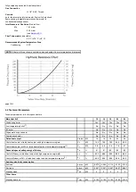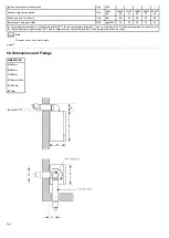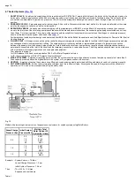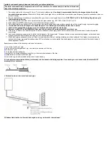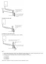
NOTE Where a vessel of the calculated size is not obtainable then the next available larger size should be used.
Fig. 14
page 16
7.0 Site Requirements
7.1 Location
NOTE: Due to the high efficiency of the boiler a plume of water vapour will be discharged from the flue.
This should be taken into account when siting the flue terminal.
1. The boiler may be fitted to any suitable wall with the flue passing through an outside wall or roof and discharging to atmosphere in a position permitting
satisfactory removal of combustion products and providing an adequate air supply. The boiler should be fitted within the building unless otherwise
protected by a suitable enclosure i.e. garage or outhouse. (The boiler may be fitted inside a cupboard - see
).
2. If the boiler is sited in an unheated enclosure then it is recommended to incorporate an appropriate device for frost protection in the system controls.
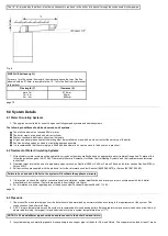
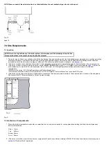
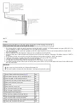
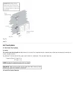
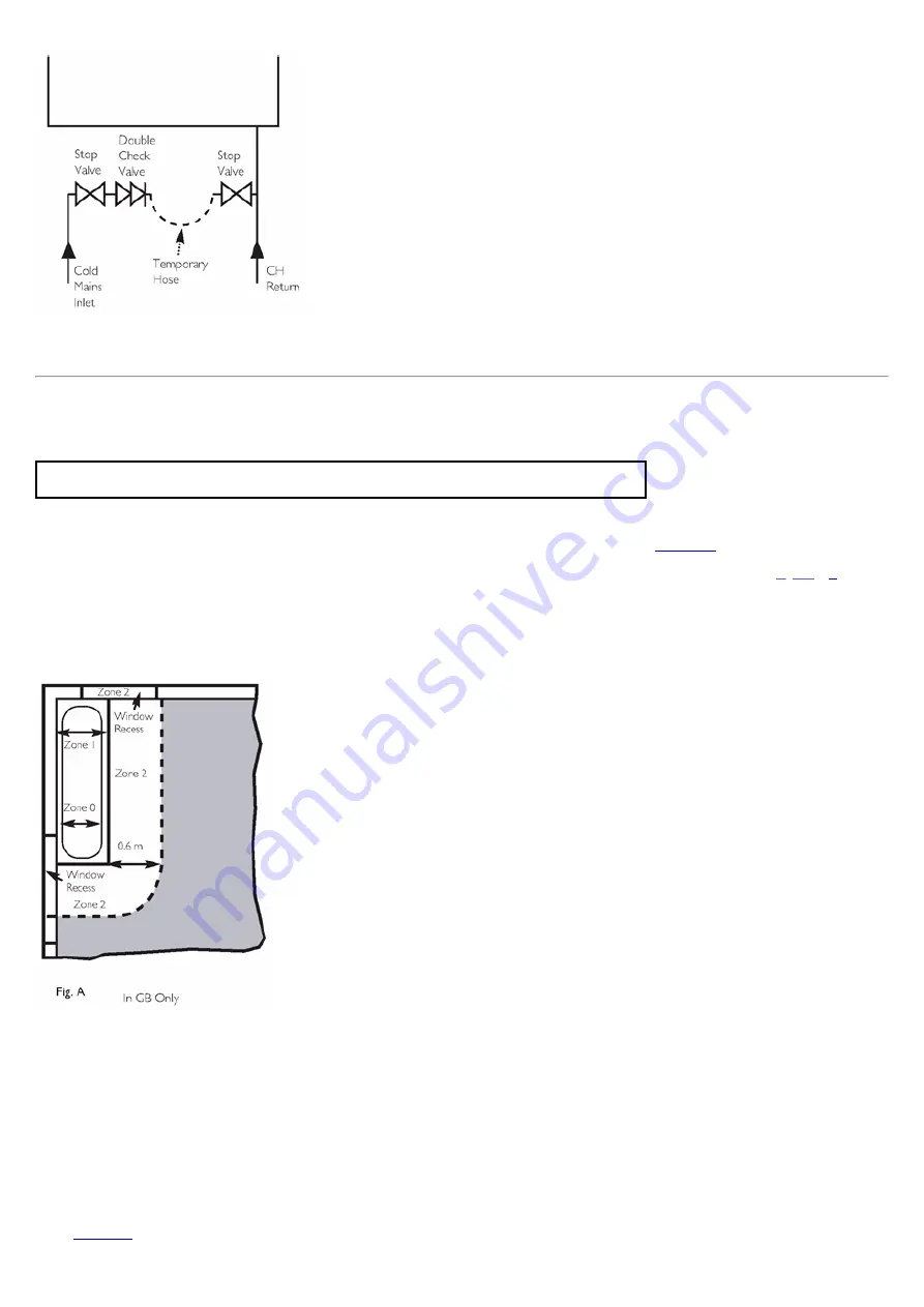
3. If the boiler is fitted in a room containing a bath or shower it
MUST NOT BE
fitted in zone 0, 1 or 2,
ONLY
within the shaded area (
shows
zone dimensions for a bathtub. For other examples refer to the Current I.E.E. Wiring Regulations) reference must be made to the relevant
requirements.
In GB this is the current I.E.E. Wiring Regulations and Building Regulations.
In IE reference should be made to the current edition of I.S. 813 "Domestic Gas Installations"
and the current ETCI rules.
4. If the boiler is to be fitted into a building of timber frame construction then reference must be made to the current edition of Institute of Gas Engineers
Publication IGE/UP/7 (Gas Installations in Timber Framed Housing).
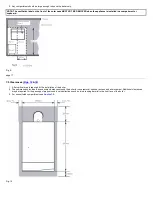
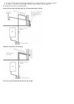
Fig. A
7.2 Ventilation of Compartments
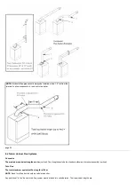
1. Where the boiler is installed in a cupboard or compartment, no air vents are required for cooling purposes providing that the minimum dimensions
below are maintained.
Sides
15mm
Top
200mm
Bottom 50mm
Front
30mm
2. If the boiler is installed in a smaller cupboard or compartment it must be ventilated according to BS 5440 Part 2 and the minimum clearances given in
maintained.
Summary of Contents for Main Heat 12
Page 8: ...Fig 3 Fig 4 Fig 5 Fig 6...
Page 38: ...Example 1 Example 2 Example 3...
Page 40: ...Fig E Fig F...
Page 51: ...Fig 31 Fig 32 Fig 33...
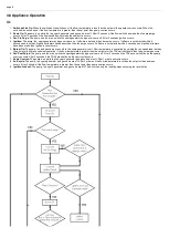
Page 55: ...Fig 35 Fig 36 page 39 12 2 Checking the Combustion 1 Follow the flow chart opposite...
Page 56: ......
Page 63: ...Fig 45 Fig 46...
Page 66: ......
Page 69: ...Fig 55 Fig 56 Fig 57 Fig 58...
Page 72: ...page 52...
Page 74: ...page 54...
Page 75: ...DRY FIRE...
Page 76: ...page 55 IGNITION LOCKOUT...
Page 77: ...page 56 OVERHEAT LOCKOUT...
Page 78: ...page 57 FAN LOCKOUT NOTE The fan is supplied with 325 Vdc...
Page 80: ...warranty This does not affect the customer s statutory rights page 62...
Page 82: ...page 63...

