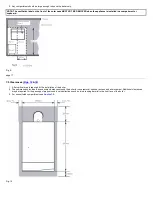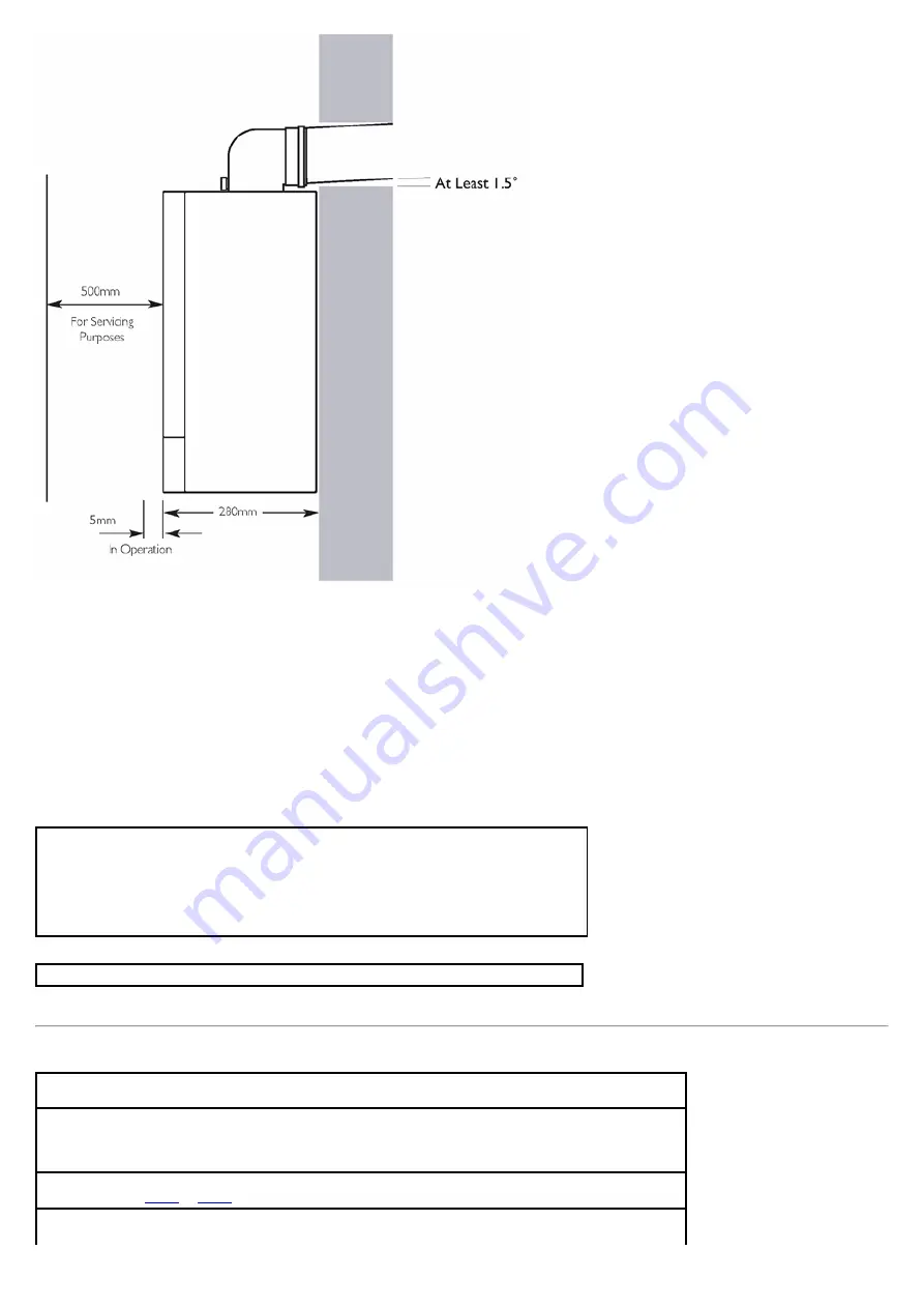
Fig. 16
7.4 Gas Supply
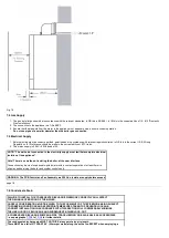
1. The gas installation should be in accordance with the relevant standards. In GB this is BS 6891. In IE this is the current edition of I.S. 813 "Domestic
Gas Installations"
.
2. The connection to the appliance is a 1/2in BSPF.
3. Ensure that the pipework from the meter to the appliance is of adequate size to ensure correct operation.
Do not use pipes of a smaller diameter than the boiler gas connection.
7.5 Electrical Supply
1. External wiring must be correctly earthed, polarised and in accordance with relevant regulations/rules. In GB this is the current I.E.E. Wiring
Regulations. In IE reference should be made to the current edition of ETCI rules.
2. The mains supply is 230V ~ 50Hz fused at 3A.
NOTE: "The method of connection to the electricity supply must facilitate complete electrical
isolation of the appliance"
.
Note! There is no method of isolating the boiler, at the user interface.
Connection may be via a fused double-pole isolator with a contact separation of at least 3mm in
all poles and servicing the boiler and system controls only.
WARNING: The PCB Control and Fan Assembly are 325 Vdc. Isolate at supply before access.
page 18
7.6 Condensate Drain
FAILURE TO INSTALL THE CONDENSATE DISCHARGE PIPEWORK CORRECTLY WILL AFFECT
THE RELIABLE OPERATION OF THE BOILER.
CAREFUL CONSIDERATION MUST BE GIVEN TO THE POSSIBILITY OF THE PIPEWORK BEING SUBJECT
TO FREEZING CONDITIONS AND APPROPRIATE MEASURES TAKEN TO PREVENT BLOCKAGE.
CORRECT INSTALLATION IN ACCORDANCE WITH THIS SECTION WILL CONSIDERABLY MINIMISE
THE LIKELIHOOD OF BLOCKAGE AND SUBSEQUENT BOILER LOCK-OUT.
A CONDENSATE DISCHARGE PUMP AND PIPE 'TRACE HEATING' ARE AVAILABLE AS ACCESSORIES
- see paragraphs
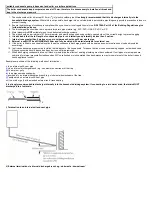
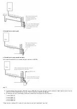
The condensate discharge pipe MUST NOT RISE at any point along its length.
There MUST be a fall of AT LEAST 2.5° (50mm per metre) along the entire run EXCEPT when employing a
Summary of Contents for Main Heat 12
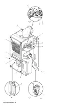
Page 8: ...Fig 3 Fig 4 Fig 5 Fig 6...
Page 38: ...Example 1 Example 2 Example 3...
Page 40: ...Fig E Fig F...
Page 51: ...Fig 31 Fig 32 Fig 33...
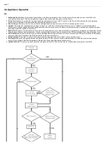
Page 55: ...Fig 35 Fig 36 page 39 12 2 Checking the Combustion 1 Follow the flow chart opposite...
Page 56: ......
Page 63: ...Fig 45 Fig 46...
Page 66: ......
Page 69: ...Fig 55 Fig 56 Fig 57 Fig 58...
Page 72: ...page 52...
Page 74: ...page 54...
Page 75: ...DRY FIRE...
Page 76: ...page 55 IGNITION LOCKOUT...
Page 77: ...page 56 OVERHEAT LOCKOUT...
Page 78: ...page 57 FAN LOCKOUT NOTE The fan is supplied with 325 Vdc...
Page 80: ...warranty This does not affect the customer s statutory rights page 62...
Page 82: ...page 63...

