suitable condensate pump in basement and cellar or similar applications.
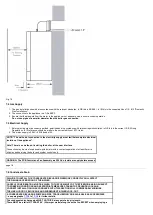
The boiler condensate trap incorporates a seal of 75mm, therefore it is unnecessary to install an air break and
trap in the discharge pipework.
1. The condensate outlet will accept 21.5mm (
3
/
4
in) plastic overflow pipe.
It is strongly recommended that this discharges internally into the
household drainage system
. Where this is not possible, discharge into an outside drain is permissible providing every possible precaution is taken to
prevent freezing.
2. Ensure the discharge of condensate complies with any national or local regulations in force.
BS 6798 & Part H1 of the Building Regulations give
further detailed guidance
.
3. The discharge pipe should be run in a proprietary drain pipe material e.g. PVC, PVC-U, ABS, PVC-C or PP.
4. Metal pipework is
NOT
suitable for use in condensate discharge systems.
5. The pipe should be a minimum of 21.5mm diameter and must be supported using suitably spaced clips of the correct design to prevent sagging.
6.
It is advisable that the full length of condensate pipe is run internally and preferably be less than 3 metres.
7.
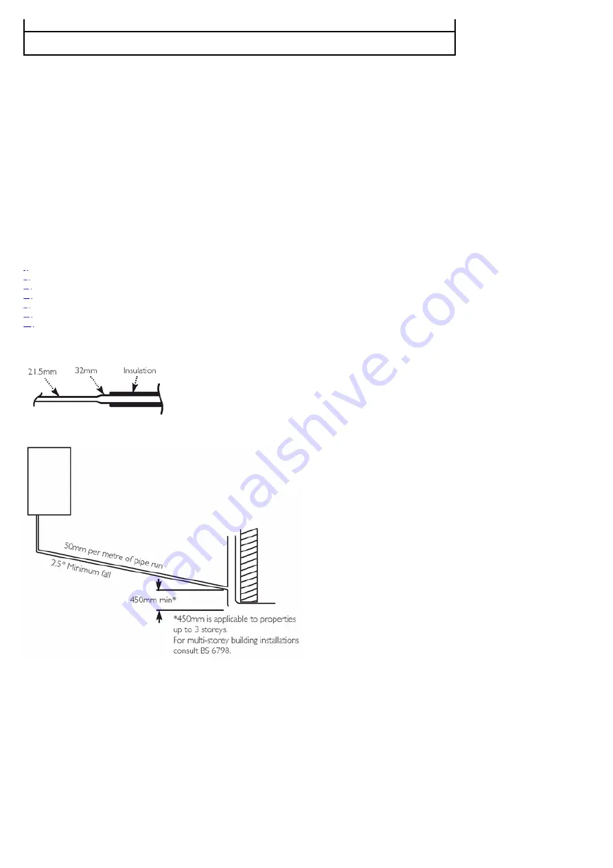
Internal runs greater than 3 metres or runs in cold areas should use 32mm waste pipe.
8.
External runs MUST be a MINIMUM of 32mm and fully insulated with material suitable for external use.
9. If the boiler is fitted in an unheated location the entire condensate discharge pipe should be treated as an external run and sized and insulated
accordingly.
10. In all cases discharge pipe must be installed to aid disposal of the condensate. To reduce the risk of condensate being trapped, as few bends and
fittings as possible should be used and any burrs on cut pipe removed.
11. When discharging condensate into a soil stack or waste pipe the effects of existing plumbing must be considered. If soil pipes or waste pipes are
subjected to internal pressure fluctuations when WC's are flushed or sinks emptied then back-pressure may force water out of the boiler trap and
cause appliance lockout.
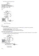
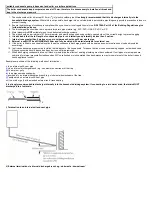
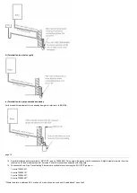
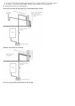
Examples are shown of the following methods of termination:-
to an internal soil & vent pipe
via an internal discharge branch (e.g. sink waste) downstream of the trap
to a drain or gully
pumped into an internal discharge branch (e.g. sink waste) downstream of the trap
pumped into an external soil & vent pipe
to a drain or gully with extended external run & trace heating
It is strongly recommended to discharge internally into the household drainage system. If connecting to a rain water drain, that drain MUST
discharge into a foul drain.
5
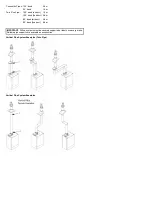
i) Termination to an internal soil and vent pipe
ii) External termination via internal discharge branch e.g. sink waste - downstream*
Summary of Contents for Main Heat 12
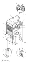
Page 8: ...Fig 3 Fig 4 Fig 5 Fig 6...
Page 38: ...Example 1 Example 2 Example 3...
Page 40: ...Fig E Fig F...
Page 51: ...Fig 31 Fig 32 Fig 33...
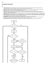
Page 55: ...Fig 35 Fig 36 page 39 12 2 Checking the Combustion 1 Follow the flow chart opposite...
Page 56: ......
Page 63: ...Fig 45 Fig 46...
Page 66: ......
Page 69: ...Fig 55 Fig 56 Fig 57 Fig 58...
Page 72: ...page 52...
Page 74: ...page 54...
Page 75: ...DRY FIRE...
Page 76: ...page 55 IGNITION LOCKOUT...
Page 77: ...page 56 OVERHEAT LOCKOUT...
Page 78: ...page 57 FAN LOCKOUT NOTE The fan is supplied with 325 Vdc...
Page 80: ...warranty This does not affect the customer s statutory rights page 62...
Page 82: ...page 63...

