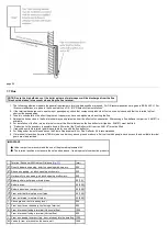
8.8 Terminal Guard (
)
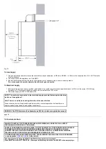
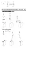
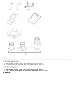
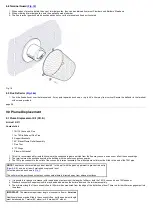
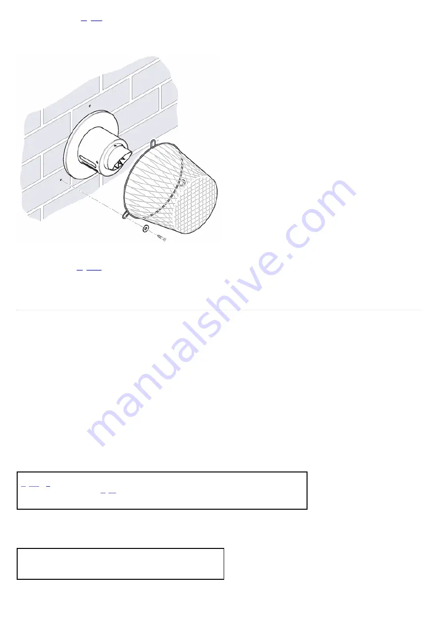
1. When codes of practice dictate the use of terminal guards, they can be obtained from most Plumbers' and Builders' Merchants.
2. When ordering a terminal guard, quote the appliance model number.
3. The flue terminal guard should be positioned centrally over the terminal and fixed as illustrated.
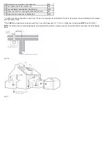
Fig. 19
8.9 Flue Deflector (
)
1. Push the flue deflector over the terminal end. It may point upwards as shown, or up to 45° either way from vertical. Secure the deflector to the terminal
with screws provided.
page 26
9.0 Plume Displacement
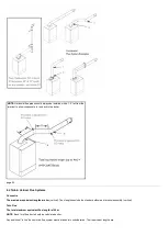
9.1 Plume Displacement Kit (P.D.K.)
Kit No 5121371
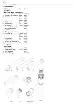
Content of kit
1 70/110 Concentric Flue
1 1m 70 Dia Exhaust Flue Pipe
2 Support Brackets
1 93° Elbow/Plume Outlet Assembly
1 Flue Trim
2 "O"
Rings
1 Elbow with Gasket
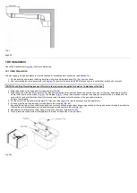
1. This kit is recommended for installations where the condensate plume emitted from the flue may cause a nuisance or affect the surroundings.
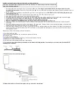
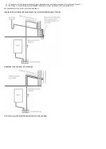
2. The terminal must be positioned outside the building with the outlet connection upwards.
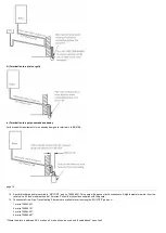
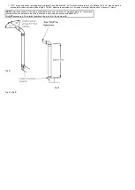
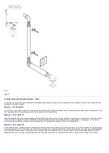
3. The 70Ø pipe connects to the outlet of the concentric terminal assembly. The elbow/plume outlet must be fitted to the end of the 70Ø pipe.
NOTE
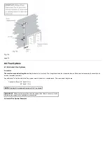
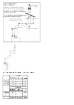
: The plume outlet must always be at least 45° to the wall, with the 'peak' uppermost to prevent rain entry
(
), and be at least 2 metres above ground level.
It must be secured as shown in
The outlet must be positioned so that any condensate plume is directed away from adjacent surfaces.
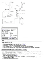
4. It is possible to reduce or increase (with the addition of extensions) the length of either or both the 70/110 concentric and 70Ø exhaust.
5. Standard concentric flue extension kits may be added between the boiler elbow and the terminal assembly.
6. The minimum length of the concentric flue is 100mm when measured from the edge of the boiler flue elbow. There is a further 45mm engagement into
the elbow.
IMPORTANT
: The maximum equivalent length of concentric flue is:-
4 metres
Additional elbows may be fitted in the concentric flue, but the equivalent length
must be reduced by 1 metre (93° elbow) or 0.5 metres (45° elbow).
Summary of Contents for Main Heat 12
Page 8: ...Fig 3 Fig 4 Fig 5 Fig 6...
Page 38: ...Example 1 Example 2 Example 3...
Page 40: ...Fig E Fig F...
Page 51: ...Fig 31 Fig 32 Fig 33...
Page 55: ...Fig 35 Fig 36 page 39 12 2 Checking the Combustion 1 Follow the flow chart opposite...
Page 56: ......
Page 63: ...Fig 45 Fig 46...
Page 66: ......
Page 69: ...Fig 55 Fig 56 Fig 57 Fig 58...
Page 72: ...page 52...
Page 74: ...page 54...
Page 75: ...DRY FIRE...
Page 76: ...page 55 IGNITION LOCKOUT...
Page 77: ...page 56 OVERHEAT LOCKOUT...
Page 78: ...page 57 FAN LOCKOUT NOTE The fan is supplied with 325 Vdc...
Page 80: ...warranty This does not affect the customer s statutory rights page 62...
Page 82: ...page 63...

