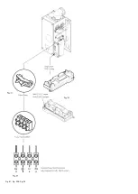
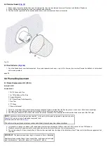
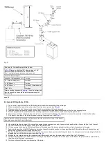
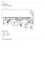
background image

Fig. J

page 30

10.0 Installation

Check Site Requirements (

section 7

before commencing.

10.1 Initial Preparation

The gas supply, gas type and pressure must be checked for suitability before connection (see 

Section 7.4

).

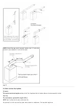
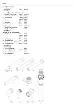
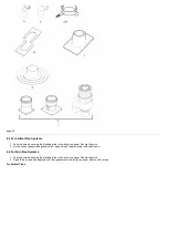
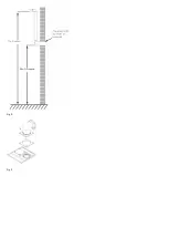
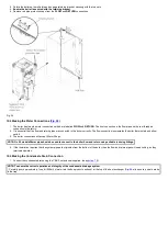
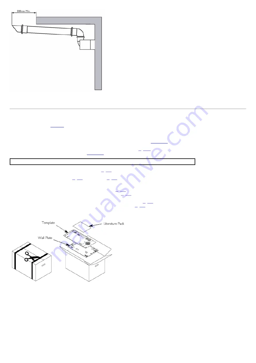
1.  Cut the banding and remove the fixing template, wall plate and literature pack (

Fig. 19a

from the carton.

2.  After considering the site requirements (see 

Section 7.0

position the template on the wall ensuring it is level both horizontally and vertically.

NOTE: When fitting Plume Displacement Kit refer to the instructions supplied for details of installation of the flue.

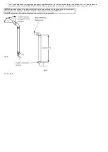
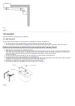
3.  Mark the position of the fixing holes for the wall plate (

Fig. 20

).

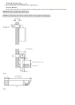
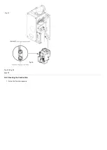
4.  Mark the centre of the flue hole (rear exit). For side exit: project the horizontal side flue centre line into the corner of the room and along the wall to

where the flue hole will be drilled. (
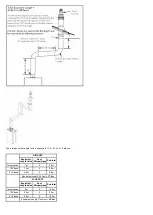
Fig. 20

). The diagram (

Fig. 21

shows the dimensions required to ensure any horizontal flue is installed with the

correct fall to the boiler. Mark the offset (V) dimension and if required, mark the position of the gas and water pipes.
Remove the template.

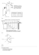
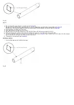
5.  Cut the hole for the flue (minimum diameter 127mm, see table (

Fig. 20

for wall thicknesses and flue diameters).

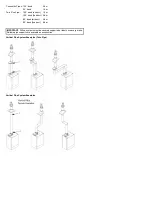
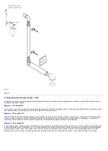
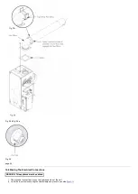
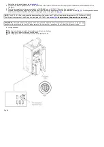
6.  Drill and plug the wall as previously marked. Secure the wall plate (

Fig. 22

).

7.  Ensuring the wall plate is level both horizontally and vertically, drill and plug at least 5 securing positions at the top and bottom through the wall plate.

Utilising the slots available ensure the wall plate is square and secure to the wall (

Fig. 22

).

8.  Additionally drill 2 relief holes 10mm deep in the wall as shown on template (

Fig. 22

).

9.  Loosely route the condensate discharge pipe to the lower left hand side of the wall plate.


Fig. 19a

Summary of Contents for Main Heat 12

Page 1: ...certification scheme for gas heating appliances These arrangements represent a change from the situation whereby compliance with Building Regulations was accepted as being demonstrated by completion o...

Page 2: ...re reference Installers are required to carry out installation commissioning and servicing work in accordance with the Benchmark Code of Practice which is available from the Heating and Hotwater Indus...

Page 3: ...anufacture The appliance is suitable only for installation in GB and IE and should be installed in accordance with the rules in force and only used in a suitably ventilated location In GB the installa...

Page 4: ...or sealed water systems BS 7593 Treatment of water in domestic hot water central heating systems IMPORTANT Installation Commissioning Service Repair This appliance must be installed in accordance with...

Page 5: ...centre of gravity repositioning yourself as necessary See section 10 3 of these instructions for recommended lift points Remember The circumstances of each installation are different Always asses the...

Page 6: ...G20 4 The boiler is suitable for fully pumped open vented central heating and domestic hot water systems and sealed systems 5 A label giving details of the model serial number and Gas Council number...

Page 7: ...re abrasion In these instances a suitable dust mask and goggles should be worn Always thoroughly wash hands after installation servicing or changing components When disposing of any items manufactured...

Page 8: ...Fig 3 Fig 4 Fig 5 Fig 6...

Page 9: ...and 5 ignition attempts have been made then ignition lockout occurs 5 Burner On The pump fan and gas valve are on while the spark generator is off Flow temperature is controlled by varying the fan spe...

Page 10: ...11 82 9 14 15 model kW 15 24 9 14 18 model kW 17 81 9 14 24 model kW 22 00 9 14 30 model kW 30 18 9 14 Heat Output Pnc Gross Condensing 40 C Mean Water Temp Max Min 12 model kW 12 81 15 model kW 16 4...

Page 11: ...2mm Condensate Drain 1 in BSP Outercase Dimensions Overall Height Inc Flue Elbow 750mm Casing Height 600mm Casing Width 390mm Casing Depth 280mm Clearances For unventilated compartments see Section 7...

Page 12: ...oiler 1 No No No No No B1 boiler No No No No No Cogeneration space heater No No No No No Combination heater No No No No No Rated heat output Prated kW 12 15 18 24 30 Useful heat output at rated heat o...

Page 13: ...0 20 19 24 1 Low temperature means for condensing boilers 30 C for low temperature boilers 37 C and for other heaters 50 C return temperature at heater inlet 2 High temperature regime means 60 C retur...

Page 14: ...en in BS 7593 Treatment of Water in Domestic Hot Water Central Heating Systems and the treatment manufacturers instructions 2 Treatment must involve the use of a proprietary cleanser such as Sentinel...

Page 15: ...iler b The pump must be fitted on the flow c The pump must be fitted in accordance with the pump manufacturer s instructions d The open vent pipe must be taken up from a tee in a horizontal section of...

Page 16: ...ure and time control to both the heating and hot water circuits and have a boiler interlock 3 The boiler should be controlled so that it operates on demand only Where it is proposed to effect control...

Page 17: ...CH Interlocked By Boiler Flow Switch Room Thermostat should not be fitted Pump must be run from Boiler P F connection for Part L1 compliance By pass not permitted must be valved off for Part L1 compli...

Page 18: ...er loss replacement refilling The sealed primary circuits may be filled or replenished by means of a temporary connection between the primary circuit and a supply pipe provided a Listed double check v...

Page 19: ...ed in a room containing a bath or shower it MUST NOT BE fitted in zone 0 1 or 2 ONLY within the shaded area Figs A B shows zone dimensions for a bathtub For other examples refer to the Current I E E W...

Page 20: ...3 Clearances Figs 15 16 1 A flat vertical area is required for the installation of the boiler 2 These dimensions include the necessary clearances around the boiler for case removal spanner access and...

Page 21: ...no method of isolating the boiler at the user interface Connection may be via a fused double pole isolator with a contact separation of at least 3mm in all poles and servicing the boiler and system c...

Page 22: ...lly insulated with material suitable for external use 9 If the boiler is fitted in an unheated location the entire condensate discharge pipe should be treated as an external run and sized and insulate...

Page 23: ...his pump will dispose of both condensate high temperature water from the relief valve It has a maximum head of 5 metres Follow the instructions supplied with the pump 13 Condensate Drain Pipe Trace He...

Page 24: ...of a Trace Heating Element is NOT a substitute for correct installation of the condensate drain ALL requirements in this section must still be adhered to v pumped into an internal discharge branch e g...

Page 25: ...If required a suitable terminal guard is available for use with the flue deflector 8 For fitting under low soffits and eaves the Plume Displacement Kit or Flue Deflector Kit is recommended 9 If a ter...

Page 26: ...n the terminal should be no nearer than 150 mm to an opening in the building fabric formed for the purpose of accommodating a built in element such as a window frame 2 Only ONE 25mm clearance is allow...

Page 27: ...al and terminal assembly vertical Any additional in line bends in the flue system must be taken into consideration Their equivalent lengths are Concentric Pipes 45 bend 0 5 m 93 bend 1 0 m NOTE Flue l...

Page 28: ...ue Systems Concentric The maximum equivalent lengths are 4m vertical Their lengths exclude the standard elbow and terminal assembly vertical Twin Flue The total maximum equivalent flue length is 150m...

Page 29: ...1 3 m 135 bend flue duct 2 6 m 90 bend air duct 4 8 m 90 bend flue duct 9 6 m IMPORTANT All flue systems must be securely supported at least once every metre Suitable pipe supports are available as ac...

Page 30: ...ue No of fittings pipes Sub total 1m extension 1m 5 5 0m 135 bend 1 3m 2 2 6m 91 5 bend 4 8m 2 9 6m Equivalent Length Air Duct 17 2m FLUE DUCT Equivalent Length Value No of fittings pipes Sub total 1m...

Page 31: ...89 U Pipe Support 110mm 243014BAX T Vertical Flue Boiler Adaptor 5106888 S Flue Terminal Deflector 248167 FLUE GROUP P Twin Flue System 80mm diameter E Flue Extension 1000mm 246137 500mm 246136 250mm...

Page 32: ...2 Fix the vertical adaptor and gasket to the top panel with the previously removed screws 8 5 For Twin Flue Systems 1 Undo the screws securing the blanking plate to the boiler top panel Discard the p...

Page 33: ...rom inside the roof adjust the flue to a vertical position and secure to the roof structure with the clamp supplied 2 For flat roof installations the aluminium flashing must be incorporated into the r...

Page 34: ...lue lengths between 270mm 105 8 and 800mm 32 from elbow to terminal Fig 18 The maximum permissible equivalent flue length is 4 metres NOTE Each additional 45 of flue bend will account for an equivalen...

Page 35: ...l must be positioned outside the building with the outlet connection upwards 3 The 70 pipe connects to the outlet of the concentric terminal assembly The elbow plume outlet must be fitted to the end o...

Page 36: ...elbows are equivalent to 3 5 metres of straight length and 45 elbows to 1 metre NOTE Permitted positions of the plume outlet relative to doors windows etc are the same as for conventional concentric...

Page 37: ...concentric flue and 4 metres of 70 exhaust were required the values could be applied to the graph as shown in Example 2 As the point of intersection of the dotted lines is below the solid diagonal li...

Page 38: ...Example 1 Example 2 Example 3...

Page 39: ...lue elbow 7 Fit the boiler flue elbow to the boiler top panel ensuring the gasket is in place Fig F Ensure that the concentric assembly is horizontal and that the external air inlet is to the bottom A...

Page 40: ...Fig E Fig F...

Page 41: ...utlet MUST remain in free air 17 It is also possible to separate the plume outlet from the 93 elbow to allow the flue to be installed as shown in Fig H 18 When the plume outlet is positioned under a b...

Page 42: ...nto the corner of the room and along the wall to where the flue hole will be drilled Fig 20 The diagram Fig 21 shows the dimensions required to ensure any horizontal flue is installed with the correct...

Page 43: ...Fig 20 Fig 21 Fig 22 page 31 10 2 Preparing The Boiler 1 Remove the outer carton and packaging 2 Lift the outercase upwards and remove 3 Remove the internal packaging...

Page 44: ...r to the wall plate using the lifting points shown in Fig 24 and locate the rear bottom edge onto the self locating support at the base of the wall plate See Safe Manual Handling NOTE When installing...

Page 45: ...he boiler thermostats and a flow switch 3 The boiler connections will accept 22mm fittings NOTE On 30 models 28mm pipe should be used to connect to the boiler flow and return using suitable reducing f...

Page 46: ...hs 270mm minimum to 800mm maximum measured from the edge of the flue elbow outlet Rear Flue maximum wall thickness 630mm Side Flue maximum wall thickness 565mm left or right 2 For rear exit measure th...

Page 47: ...dicated Fig 27 Check your dimensions The flue tubes are fixed together Cut through both tubes whilst resting the flue on the semi circular packing pieces Deburr both tube ends IMPORTANT Check all meas...

Page 48: ...ough the hole in the wall 10 Engage the elbow on to the flue connection on top of the boiler Secure with the four screws supplied in the kit 11 Make good between the wall and air duct outside the buil...

Page 49: ...35 10 8 Making The Electrical Connections WARNING This appliance must be earthed 1 The electrical connections are on the right hand side of the unit 2 Undo the two screws securing the cable clamp and...

Page 50: ...Red jumper labelled CN12 from the bottom left hand side of the PCB c Hinge back up the PCB housing and secure with screw 4 Route the incoming electrical cable s through the grommet in the support brac...

Page 51: ...Fig 31 Fig 32 Fig 33...

Page 52: ...e 36 11 0 Electrical 11 1 Schematic Wiring Diagram Key To Wiring Colours b Blue r Red bk Black g Green w White g y Green Yellow br Brown op Opaque gy Grey y Yellow page 37 11 2 Illustrated Wiring Diag...

Page 53: ...ce should be made to BS EN 12828 14336 when commissioning the boiler 2 At the time of commissioning complete all relevant sections of the Benchmark Checklist at the rear of this publications 3 Flush t...

Page 54: ...ig 34 NOTE The 12 15 18 24 are self regulating dependent upon the system load The 30 will modulate between inputs of 33 76kW and 10 3kW The 30 input is factory set at 24 5kW and can be altered to 33 7...

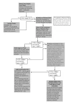
Page 55: ...Fig 35 Fig 36 page 39 12 2 Checking the Combustion 1 Follow the flow chart opposite...

Page 56: ......

Page 57: ...ews supplied in the kit secure the outercase to the combustion box Fig 37 3 Hinge up the lower door panel Fig 38 4 The Important Ventilation Information label can be removed unless the appliance is in...

Page 58: ...Servicing must be performed by a competent person in accordance with B S 7967 4 2 After servicing complete the relevant Service Interval Record section of the Benchmark Commissioning Checklist at the...

Page 59: ...gas pressure and gas rate are satisfactory either Perform the Annual Servicing Inspection Section 14 2 re check Replace the gas valve Section 15 8 re check page 43 14 2 Annual Servicing Inspection 1...

Page 60: ...e trap and disconnect the sensor leads Fig 43 g Remove the two screws securing the burner and remove the burner Visually inspect the internal burner baffle for obstruction check seal around baffle for...

Page 61: ...ical Data 13 If the ratio or level is greater than that quoted telephone the Technical Enquiries for further advice IMPORTANT No adjustment of the gas valve is permissible 14 Complete the relevant Ser...

Page 62: ...may affect combustion e g fan 1 Before changing any components please read Section 1 2 Important Information 2 Remove the outer case and lower door panel see Fitting the Outercase Section 13 0 0 WARN...

Page 63: ...Fig 45 Fig 46...

Page 64: ...ical connection 5 Pull pipe away from flowswitch 6 Remove the two screws securing the flowswitch to the boiler 7 Remove the flowswitch 8 Fit the new flowswitch and reassemble in reverse order 9 Recomm...

Page 65: ...ew electrodes and new gasket as required and reassemble in reverse order 15 6 Fan Fig 52 WARNING The PCB Control and Fan Assembly are 325 Vdc Isolate at supply before access 1 Loosen the screw holding...

Page 66: ......

Page 67: ...rical plug from the gas valve 5 Remove the fan see section 15 6 and injector pipe 6 Remove the two gas valve securing screws from inside the air box holding the gas valve 7 Remove the gas valve from t...

Page 68: ...nd heat exchanger can be changed after removal of the combustion box door To change the heat exchanger the fan and burner must be removed first see section 15 6 and 15 10 1 Remove the combustion box d...

Page 69: ...Fig 55 Fig 56 Fig 57 Fig 58...

Page 70: ...page 50 15 12 Heat Exchanger Lower Insulation Pad Fig 60 1 Remove all components in the base of the airbox 2 Remove the burner see section 15 10 3 Remove the four bolts securing the combustion box bas...

Page 71: ...erature Thermistor Red 240670 B E06 059 Flow Switch 242459 C E58 912 Safety Thermostat Black 242235 D H46 830 PCB 5121025 E Fan 5109925 F H13 184 Gas Valve 241900 G E06 085 Viewing Window 242484 H H17...

Page 72: ...page 52...

Page 73: ...s supplied with 325 Vdc Fan Fault Finding should only be carried out after the boiler has been electrically isolated General Fault Finding should only be carried out by someone who is appropriately qu...

Page 74: ...page 54...

Page 75: ...DRY FIRE...

Page 76: ...page 55 IGNITION LOCKOUT...

Page 77: ...page 56 OVERHEAT LOCKOUT...

Page 78: ...page 57 FAN LOCKOUT NOTE The fan is supplied with 325 Vdc...

Page 79: ...sioning Checklist is to be completed in full by the competent person who commissioned the boiler as a means of demonstrating compliance with the appropriate Building Regulations and then handed to the...

Page 80: ...warranty This does not affect the customer s statutory rights page 62...

Page 81: ...tem is serviced regularly and that the appropriate Service Interval Record is completed Service Provider Before completing the appropriate Service Record below please ensure you have carried out the s...

Page 82: ...page 63...

Page 83: ...s visit www baxi co uk terms Failure to adhere to terms and conditions will void your manufacturer s warranty Baxi Brooks House Coventry Road Warwick CV34 4LL Please ensure the boiler is installed in...

Reviews: