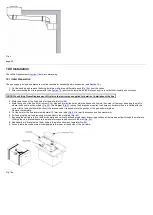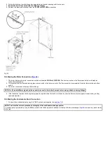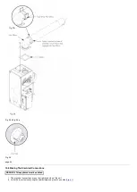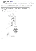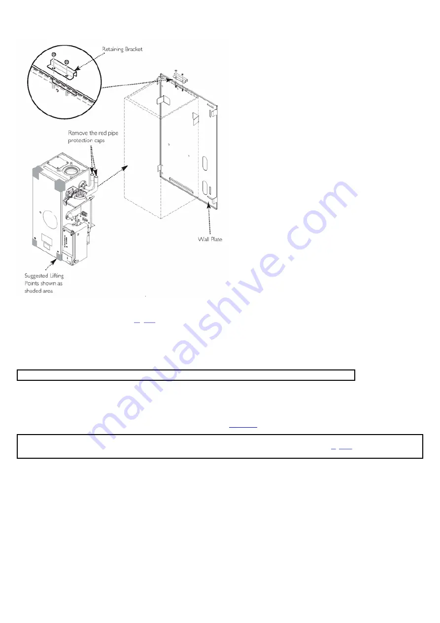
3. Rotate the boiler up to wall plate and engage retaining bracket, securing with the two nuts.
4.
Ensure the boiler is secured with the retaining bracket.
5. Remove red pipe protection caps from the
FLOW
and
RETURN
connections.
Fig. 24
10.4 Making the Water Connections (
)
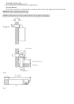
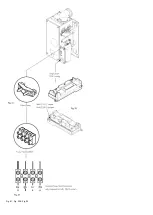
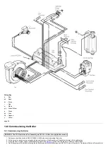
1. The boiler has two side water connections which are labelled
FLOW
and
RETURN
. The front connection is the flow pipe and the rear threaded
connection is the return.
2. It is essential that the flow and return pipes are connected to the boiler correctly. The flow connection incorporates the boiler thermostats and a flow
switch.
3. The boiler connections will accept 22mm fittings.
NOTE: On 30 models 28mm pipe should be used to connect to the boiler flow and return using suitable reducing fittings.
4. If the installation requires that the system pipework originates from the bottom of the boiler, then the flow and return pipes will need cutting, as they
terminate upwards.
10.5 Making the Condensate Drain Connection
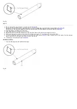
1. Connect the condensate drain using the 1"
BSP nut and seal supplied. (see
).
NOTE: To ensure the correct operation and integrity of the condensate drainage system
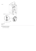
- Carefully pour approximately 1 cupful (250ml) of water into the flue products exhaust, at the top of the heat exchanger (
) to ensure a seal is made
in the trap.
Summary of Contents for Main Heat 12
Page 8: ...Fig 3 Fig 4 Fig 5 Fig 6...
Page 38: ...Example 1 Example 2 Example 3...
Page 40: ...Fig E Fig F...
Page 51: ...Fig 31 Fig 32 Fig 33...
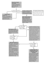
Page 55: ...Fig 35 Fig 36 page 39 12 2 Checking the Combustion 1 Follow the flow chart opposite...
Page 56: ......
Page 63: ...Fig 45 Fig 46...
Page 66: ......
Page 69: ...Fig 55 Fig 56 Fig 57 Fig 58...
Page 72: ...page 52...
Page 74: ...page 54...
Page 75: ...DRY FIRE...
Page 76: ...page 55 IGNITION LOCKOUT...
Page 77: ...page 56 OVERHEAT LOCKOUT...
Page 78: ...page 57 FAN LOCKOUT NOTE The fan is supplied with 325 Vdc...
Page 80: ...warranty This does not affect the customer s statutory rights page 62...
Page 82: ...page 63...

