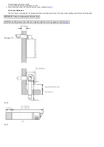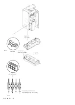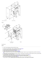
Fig. 27a
page 34
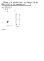
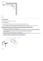
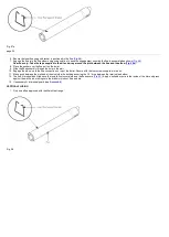
6. Ensure the inner flue support bracket is positioned in the flue (
7. Engage the flue into the flue elbow using soap solution to ease the engagement ensuring the flue is assembled as shown (
).
Rear flue only:- Take the tape supplied in the kit and wrap around the joint between the flue and the elbow (
8. Place the gasket over the flue exit on the boiler.
9. Slide the flue assembly through the hole in the wall.
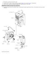
10. Engage the elbow on to the flue connection on top of the boiler. Secure with the four screws supplied in the kit.
11. Make good between the wall and air duct outside the building ensuring the 1.5° drop between the terminal and elbow.
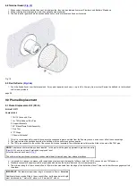
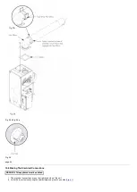
12. The flue trim should be fitted once the installation is complete and the flue secure (
). Apply a suitable mastic to the inside of the trim and press
against the wall finish, making sure the brickwork is dust free and dry.
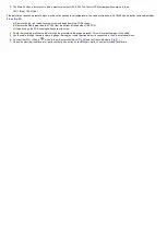
13. If necessary fit a terminal guard (see
).
VERTICAL FLUEING
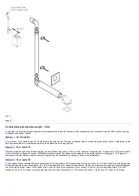
1. Only use a flue approved with the Main Heat range.
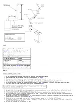
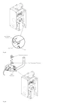
Fig. 28
Summary of Contents for Main Heat 12
Page 8: ...Fig 3 Fig 4 Fig 5 Fig 6...
Page 38: ...Example 1 Example 2 Example 3...
Page 40: ...Fig E Fig F...
Page 51: ...Fig 31 Fig 32 Fig 33...
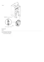
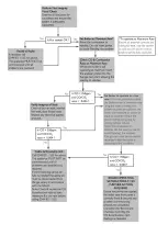
Page 55: ...Fig 35 Fig 36 page 39 12 2 Checking the Combustion 1 Follow the flow chart opposite...
Page 56: ......
Page 63: ...Fig 45 Fig 46...
Page 66: ......
Page 69: ...Fig 55 Fig 56 Fig 57 Fig 58...
Page 72: ...page 52...
Page 74: ...page 54...
Page 75: ...DRY FIRE...
Page 76: ...page 55 IGNITION LOCKOUT...
Page 77: ...page 56 OVERHEAT LOCKOUT...
Page 78: ...page 57 FAN LOCKOUT NOTE The fan is supplied with 325 Vdc...
Page 80: ...warranty This does not affect the customer s statutory rights page 62...
Page 82: ...page 63...


