page 8
3.0 Appliance Operation
3.1
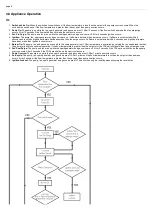
1.
Switched Live On:
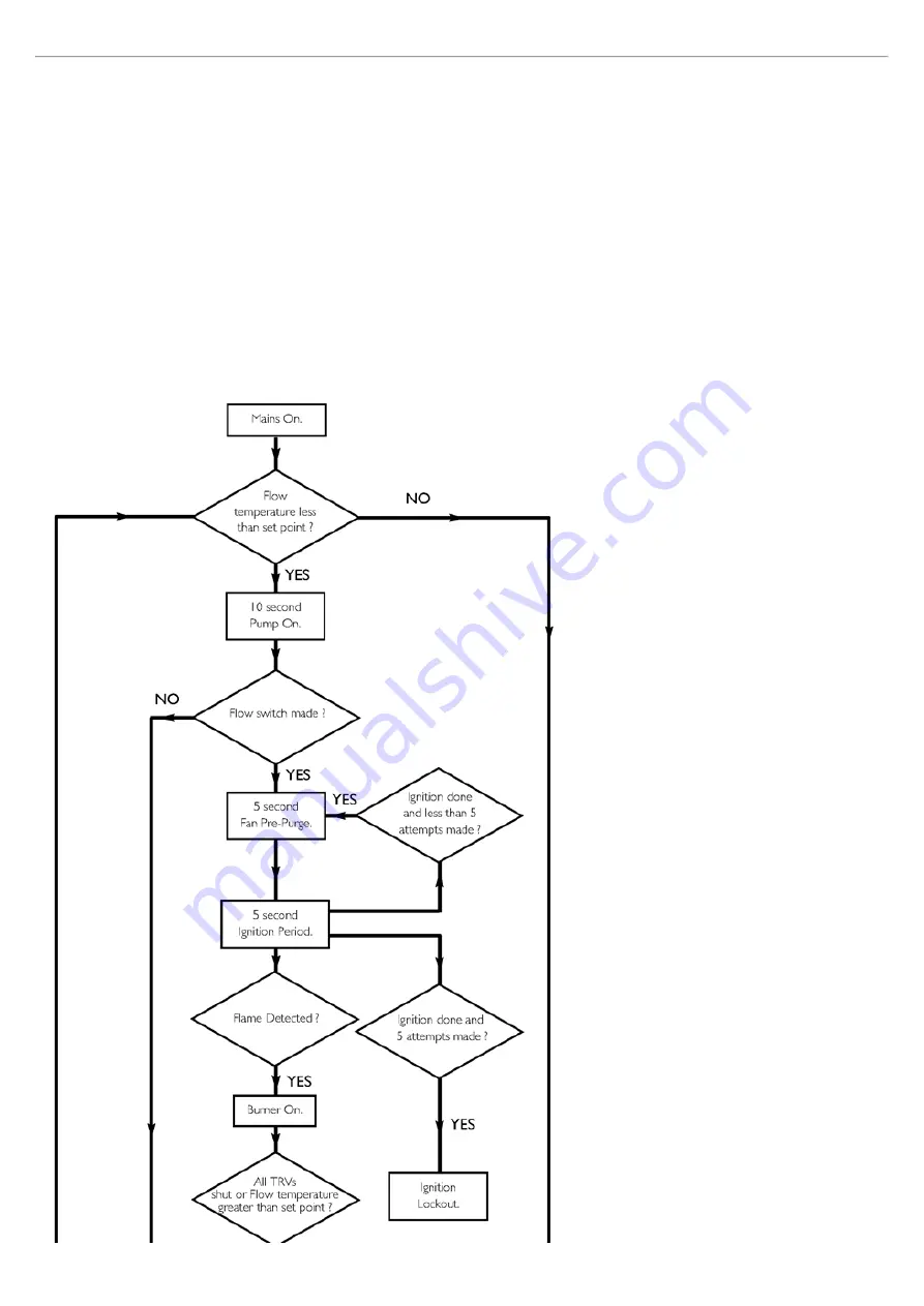
When the switched live switches on if the flow temperature is less than the set point then pump overrun occurs. When the
switched live switches on if the flow temperature is greater than the set point then pump overrun occurs.
2.
Pump On:
The pump is on while the fan, spark generator and gas valve are off. After 10 seconds if the flow switch has made then fan pre-purge
occurs. After 10 seconds if the flow switch has not made then anticycle occurs.
3.
Fan Pre-Purge:
The pump and fan are on while the spark generator and gas valve are off. After 5 seconds ignition occurs.
4.
Ignition:
The pump, fan, spark generator and gas valve are on. If a flame is detected then burner on occurs. If a flame is not detected within 5
seconds and less than 5 ignition attempts have been made then fan purge occurs. If a flame is not detected within 5 seconds and 5 ignition attempts
have been made then ignition lockout occurs.
5.
Burner On:
The pump, fan and gas valve are on while the spark generator is off. Flow temperature is controlled by varying the fan speed (and thereby
the gas rate) to achieve optimum operation. If the flow temperature is greater than the set point or the TRVs all shut down then fan post purge occurs.
6.
Fan Post Purge:
The pump and fan are on while the spark generator and gas valve are off. After 5 seconds if the TRVs are not shut down then pump
overrun occurs. After 5 seconds if the TRVs are shut down then anti-cycle occurs.
7.
Pump Overrun:
The pump is on while the fan, spark generator and gas valve are off. After 1 minute anticycle occurs.
8.
Anti-cycle:
The pump, fan, spark generator and gas valve are off. After 3 minutes if the flow temperature is less than the set point then pump on
occurs. After 3 minutes if the flow temperature is greater than the set point then pump overrun occurs.
9.
Ignition Lockout:
The pump, fan, spark generator and gas valve are off. The boiler can only be reset by manually using the reset button.
Summary of Contents for Main Heat 12
Page 8: ...Fig 3 Fig 4 Fig 5 Fig 6...
Page 38: ...Example 1 Example 2 Example 3...
Page 40: ...Fig E Fig F...
Page 51: ...Fig 31 Fig 32 Fig 33...
Page 55: ...Fig 35 Fig 36 page 39 12 2 Checking the Combustion 1 Follow the flow chart opposite...
Page 56: ......
Page 63: ...Fig 45 Fig 46...
Page 66: ......
Page 69: ...Fig 55 Fig 56 Fig 57 Fig 58...
Page 72: ...page 52...
Page 74: ...page 54...
Page 75: ...DRY FIRE...
Page 76: ...page 55 IGNITION LOCKOUT...
Page 77: ...page 56 OVERHEAT LOCKOUT...
Page 78: ...page 57 FAN LOCKOUT NOTE The fan is supplied with 325 Vdc...
Page 80: ...warranty This does not affect the customer s statutory rights page 62...
Page 82: ...page 63...


