background image

2

1

0

4

3

bar

Reset

Burner On

Flame Failure

Power On

3

Operating the Boiler

The Central Heating and Hot Water you need will
be available when the gas and electricity supplies
to the boiler are turned on with the timer and other
heating controls in your system set correctly.

Other heating controls are items such as
room thermostats, cylinder thermostats
and thermostatic radiator valves. To give
the most energy efficient performance
these controls can switch your boiler on
and off even when your timer is on.
Instructions on how to use your
programmer and other heating controls
should have been supplied with the items.
Baxi Potterton also produce a guide ‘How
to get the best out of your NEW Central
Heating System’. Telephone our Literature
Hotline on 

08706 060 623

to request your

free copy.

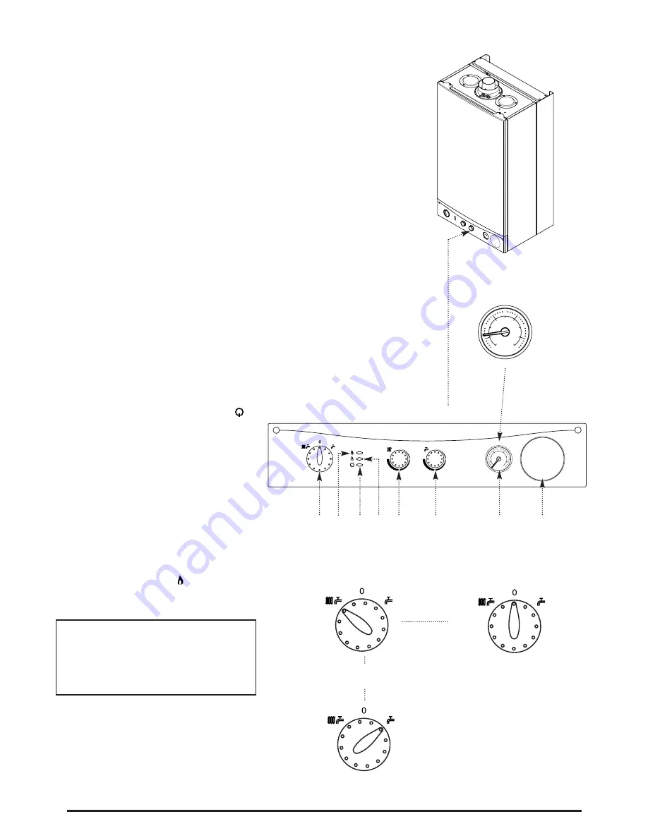
1. Ensure that the electricity and gas supplies are
turned on. Check that the central heating pressure
is between 0.5 and 1.0 bar (Fig. 1).

2. Turn the On/Off/Reset selector switch either
anti-clockwise from the off position (Fig. 3) to both
central heating and domestic hot water or
clockwise to domestic hot water only.

3. In either position the green “power” neon (     )
will illuminate (Fig. 2).

4. 

Position (i)

In this position the central heating

will operate according to demand or provide
domestic hot water when a tap or shower is turned
on (Fig. 4). Priority is given to domestic hot water.

5. 

Position (ii)

In this position hot water will be

provided when a tap or shower is turned on (Fig.
5).

6. The boiler will light automatically on demand.

7. The orange “burner” neon (     ) will illuminate
when the boiler is operating and the main burner
is on (Fig. 2).

IMPORTANT:

When the selector switch is in

the ‘0’ (Off) position the electrical supply to the
boiler is isolated. The boiler will not operate
and the integral timer (if fitted) will require
resetting once the selector switch is set to
either Position (i) or Position (ii).

Reset

Reset

Position (ii)

(Hot Water)

Fig. 4

Fig. 5

Reset

OFF Position

Fig. 3

Fig. 2

Fig. 1

1.

On/Off/Reset Selector Switch

2.

Burner On & Fault Indicator Neon

3.

Power Neon

4.

Flame Failure & Fault Indicator Neon

5.

Central Heating Temperature Control

6.

Hot Water Temperature Control

7.

Central Heating System Pressure Gauge

8.

Optional Integral Timer Position

1

2

3

4

5

6

7

8

2

1

0

4

3

bar

Position (i) 

(Central Heating or Hot Water)

Summary of Contents for Combi 24 HE

Page 1: ...ons 1993 No 3083 and is deemed to meet the requirements of Directive 92 42 EEC on the energy efficiency requirements for new hot water boilers fired with liquid or gaseous fuels Type test for purpose...

Page 2: ...eer visit either in warranty or out please call heateam on 08701 655 644 It would help if you had your boiler serial number when you call the serial number is shown on the back cover of this guide Ann...

Page 3: ...nd domestic hot water or clockwise to domestic hot water only 3 In either position the green power neon will illuminate Fig 2 4 Position i In this position the central heating will operate according t...

Page 4: ...selector switch fully anti clockwise against the spring pressure to the Reset position and hold for at least 2 seconds If this occurs repeatedly contact your Installer or Service Engineer If the boil...

Page 5: ...stic hot water can be adjusted by turning the control knob clockwise to increase up to a maximum of 65 C Fig 7 5 The temperature of the water is also dependent on the water flow rate and the temperatu...

Page 6: ...the Boiler 1 For short periods Turn the selector switch to the OFF position Fig 12 2 For long periods Turn off the selector switch Fig 12 electricity and gas supplies If your home is to be left unocc...

Page 7: ...d heateam can provide a competitive fixed price repair rate including parts labour and VAT To find out more call heateam on 08701 655 644 open Monday to Friday 8am 6pm weekend 8 30am 2pm An appointmen...

Page 8: ...oiler Take note of any warning labels on your boiler Your boiler should have the following minimum clearances for Safety and Maintenance Top 200mm Bottom 200mm Both sides 5mm Front 5mm In Operation 45...

Page 9: ...9 Fig 13 Fig 14 2 1 0 4 3 bar Reset Burner On Flame Failure Power On 200mm Min 780mm 450mm 200mm Min 5mm Min 5mm Min 8mm Min 450mm Min For Servicing Purposes In Operation...

Page 10: ...ontinue below 3 Is the gas supply turned on 4 Is the mains water supply turned on 5 Is the system pressure correct 6 Is the programmer or timer switch set to On Refer to the instruction booklet suppli...

Page 11: ...In an Emergency If a water or gas leak occurs or is suspected the boiler can be isolated at the inlet valves as follows 1 Turn off the electrical supply and turn the selector switch on the facia box...

Page 12: ...have the following information to hand 1 boiler serial number 2 boiler make and model number 3 Your installer name and address details 4 Proof of purchase if you do not have the boiler serial number...

Reviews: