8.0
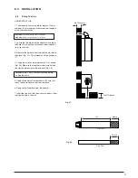
INSTALLATION
22
8.6
Fitting the Flue
(Cont)
IMPORTANT:
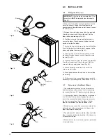
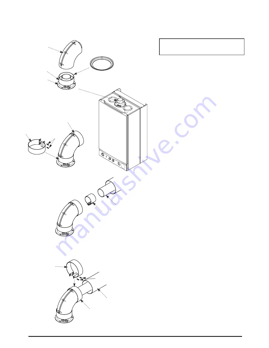
If the flue length is greater than 1.5m
the restrictor
MUST
be removed from the adaptor
(Fig. 29).
8. Take one of the rubber seals and position it on the
boiler flue adaptor. Engage the flue elbow on the
adaptor and pull the sleeve up so that it equally covers
the joint (Fig. 29).
9. Remove the screws from one of the clips provided.
Prise the clip apart and fit it over the seal. Set the
elbow to the required angle (Fig. 30).
10. Refit the screws to the clip and tighten them to
secure the elbow. Take the second rubber seal and
position it on the flue elbow.
11. Locate the flue duct clamp on the flue outlet elbow.
Draw the flue duct out of the air duct, engage it in the
clamp and tighten the screws (Fig. 31).
12. Draw the air duct out of the wall and align it with
the elbow. Position the seal so that it equally covers
the joint (Fig. 32).
13. Remove the screws from the second clip provided.
Prise the clip apart and fit it over the seal. Refit the
screws to the clip and tighten them (Fig. 32).
14. Where possible position the clips so that the
screws are not visible.
15. Make good between the wall and air duct outside
the building.
16. Fit the circular flue trim outside if required, and if
necessary fit a terminal guard (see Section 7.8 & 7.9).
8.7
Extensions & Additional Elbows
1. The method of connecting any flue extensions or
additional elbows is the same as that for connecting
the standard flue and 90° elbow as described above.
2. If, for example, when a flue extension is connected
to a 90° elbow the flue duct will project from the air
duct at the unconnected end by the same amount as
the flue duct spigot does from the elbow . Further
elbows or extensions can then be added to this.
3. Similarly, a concentric flue can be connected to the
boiler adaptor in the same manner as it does to the
elbow to provide a vertical flue.
4. The additional 90° elbow available is identical to the
elbow supplied with the standard flue. 45° elbows are
of the same principle.
5. Extensions can be cut according to the requirements
of the installation.
Fig. 29
Fig. 30
Fig. 31
Fig. 32
Elbow
Restrictor
Seal
Adaptor
Seal
Clip
Screws
Flue Duct
Clamp
Flue Duct
Air Duct
Seal
Clip
Screws
Summary of Contents for Combi 24 HE
Page 45: ...45 16 0 NOTES ...


