background image

5

CONTENTS

1.0

Introduction

6

2.0

General Layout

7

3.0

Appliance Operation

8

4.0

Technical Data

9

5.0

Dimensions and Fixings

10

6.0

System Details

11

7.0

Site Requirements

14

8.0

Installation

19

9.0

Commissioning

24

10.0 Completion

26

11.0 Servicing

27

12.0 Changing Components

29

13.0 Electrical

38

14.0 Fault Finding

39

15.0 Short Parts List

44

Benchmark Checklist

46

Section

Page

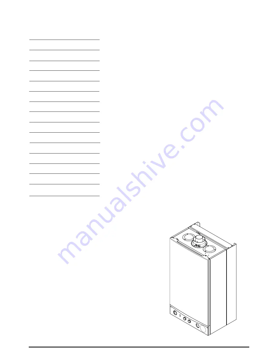
Summary of Contents for Combi 24 HE

Page 1: ...3 and is deemed to meet the requirements of Directive 92 42 EEC on the energy efficiency requirements for new hot water boilers fired with liquid or gaseous fuels Type test for purpose of Regulation 5 certified by Notified Body 0051 Product Production certified by Notified Body 0086 For use in GB IE only These instructions include the Benchmark Commissioning Checklist and should be left with the U...

Page 2: ...ark Logbook is being withdrawn However a similar document in the form of a commissioning checklist and service interval record is incorporated at the back of these instructions Baxi Potterton is a member of the Benchmark initiative and fully supports the aims of the programme Its aim is to improve the standards of installation and commissioning of central heating systems in the UK and to encourage...

Page 3: ... certificate of compliance to the property You must ensure that the notification number issued by CORGI is writen onto the Benchmark Checklist Scheme Members only Call CORGI on 0870 88 88 777 or log onto www corgi notify com within 10 days If you notify via CORGI Scheme CORGI will then notify the relevant Local Authority Building Control Scheme on member s behalf Complete the Benchmark Checklist I...

Page 4: ...uitable only for installation in GB and IE and should be installed in accordance with the rules in force and only used in a suitably ventilated location In GB the installation must be carried out by a CORGI Registered Installer It must be carried out in accordance with the relevant requirements of the Gas Safety Installation Use Regulations The appropriate Building Regulations either The Building ...

Page 5: ... Data 9 5 0 Dimensions and Fixings 10 6 0 System Details 11 7 0 Site Requirements 14 8 0 Installation 19 9 0 Commissioning 24 10 0 Completion 26 11 0 Servicing 27 12 0 Changing Components 29 13 0 Electrical 38 14 0 Fault Finding 39 15 0 Short Parts List 44 Benchmark Checklist 46 Section Page ...

Page 6: ...details of the model serial number and Gas Council number and is situated on the control box It is visible when the case front panel is removed Fig 1 6 The boiler is intended to be installed in residential commercial light industrial E M C environments on a governed meter supply only 7 The boiler must be installed with one of the purpose designed flues such as the standard horizontal flue kit part...

Page 7: ... System Pressure Gauge 11 Control PCB 12 Control Box 13 3 Way Valve Assembly 14 Flame Sensing Electrode 15 Spark Electrode 16 Burner 17 Primary Heat Exchanger 18 Fan Assembly 19 On Off Reset Selector Switch 20 Burner Neon 21 Power Neon 22 Reset Neon 23 Central Heating Temperature Control 24 Hot Water Temperature Control 18 17 16 14 15 13 12 11 10 9 19 20 21 22 23 24 10 9 7 6 3 4 5 8 2 1 2 1 0 4 3 ...

Page 8: ...he temperature sensor 4 When the domestic hot water demand ceases the burner will extinguish and the diverter valve will remain in the domestic hot water mode unless there is a demand for central heating IMPORTANT When the selector switch is in the 0 Off position the electrical supply to the boiler is isolated The boiler will not operate and the integral timer if fitted will require resetting once...

Page 9: ... Primary Water Content of Boiler unpressurised 1 0 Connections copper tails Gas Supply 22mm Central Heating Flow 22mm Central Heating Return 22mm Cold Water Mains Inlet 15mm DHW Flow 15mm Pressure Relief Discharge 15mm Temperatures C H Flow Temp adjustable 35 C to 85 C max 5 C D H W Flow Temp adjustable 35 C to 65 C max 5 C dependent upon flow rate Heat Input C H DHW Max Min kW 26 3 10 6 Btu h 89 ...

Page 10: ...07mm Ø Min E 200mm F 190mm G 143mm 360 Orientation Tube Ø 100mm D C B A E G F 65mm 65mm 65mm 65mm Wall View from under the appliance Gas Inlet Heating Flow Domestic Hot Water Outlet Cold Water Inlet Heating Return 130mm 165 7mm 95mm Left Hand Side of Boiler Fig 6 Fig 7 ...

Page 11: ...ch can lead to damage of system components All systems must be thoroughly drained and flushed out The recommended flushing and cleansing agents are Betz Dearborn Sentinel X300 or X400 and Fernox Superfloc Universal Cleanser which should be used following the flushing agent manufacturer s instructions System additives corrosion inhibitors and flushing agents descalers should be suitable for alumini...

Page 12: ... 6 6 Expansion Vessel Central Heating only 1 The appliance expansion vessel is pre charged to 0 5 bar Therefore the minimum cold fill pressure is 0 5 bar The vessel is suitable for correct operation for system capacities up to 125 litres For greater system capacities an additional expansion vessel must be fitted For GB refer to BS 7074 Pt 1 For IE the current edition of I S 813 Domestic Gas Instal...

Page 13: ...an develop which may result in damage to fittings and devices on the system 6 The boiler s maximum working mains pressure is 8 bar therefore all pipework connections fittings etc should be suitable for pressures in excess of 8 bar A pressure reducing valve must be fitted for pressures in excess of 8 bar The manufacturer of any outlet fittings such as a shower valve may require a lower maximum pres...

Page 14: ...ent I E E Wiring Regulations and Building Regulations In IE reference should be made to the current edition of I S 813 Domestic Gas Installations and the current ETCI rules 4 If the boiler is to be fitted into a building of timber frame construction then reference must be made to the current edition of Institute of Gas Engineers Publication IGE UP 7 Gas Installations in Timber Framed Housing 7 2 C...

Page 15: ... at the rear of the gas service cock Fig 14 3 Ensure that the pipework from the meter to the appliance is of adequate size Do not use pipes of a smaller diameter than the boiler gas connection 22mm 7 5 Electrical Supply 1 External wiring must be correctly earthed polarised and in accordance with relevant regulations rules In GB this is the current I E E Wiring Regulations In IE reference should be...

Page 16: ...ning 300 B Below gutters drain soil pipe 25 C Below eaves 25 D Below balcony car port roof 25 E From vertical drain pipes and soil pipes 25 F From internal or external corners 25 G Above adjacent ground or balcony level 300 H From a surface or boundary facing the terminal 600 I Facing terminals 1200 J For opening door window in car port into dwelling 1200 K Vertically from a terminal on the same w...

Page 17: ...m the adhesive seal Apply the seal to the rear of the trim flange Fig 18 3 Locate the trim over the flue terminal and push it back to the wall to compress the seal Fig 19 7 9 Terminal Guard Fig 20 1 When codes of practice dictate the use of terminal guards they can be obtained from most Plumbers and Builders Merchants 2 There must be a clearance of at least 50mm between any part of the terminal an...

Page 18: ...ation Their equivalent lengths are Concentric Pipes 45 bend 0 5 metres 90 bend 1 0 metres Twin Flue Pipe 45 bend 0 25 metres 90 bend 0 50 metres The elbow supplied with the standard horizontal flue is not included in any equivalent length calculations 5 The illustrations opposite show examples of maximum equivalent lengths 6 Instructions for guidance and fitting are included in each kit where appr...

Page 19: ...return pipe Fig 22 2 Flush thoroughly see System Details Section 6 2 8 3 Preparing The Boiler 1 Remove all packaging 2 Stand the boiler on its base by using the rear lower edge as a pivot NOTE A small amount of water may drain from the boiler in the upright position Fig 21 Fig 22 FIXING TEMPLATE 5 mm Minimum Side Clearance 5 mm Minimum Side Clearance Horizontal Side Flue Centre Line 107mm Dia Mini...

Page 20: ...lbows with flared ends to the valves 7 Ensure that the sealing washers are used on all connections The rubber washers must be used on the gas connections 8 The gas and water supplies central heating flow and return and domestic hot water flow can now be connected 8 5 Fitting the Pressure Relief Discharge Pipe Fig 25 1 Remove the discharge pipe from the kit 2 Determine the routing of the discharge ...

Page 21: ...the distance from the outside wall face to the elbow Fig 27 This dimension will be known as X 4 Taking the air duct mark dimension X as shown Fig 28 Measure the length of waste material and transfer the dimension to the flue duct Fig 28 IMPORTANT Check all measurements before cutting the ducts 5 Remove the waste from both ducts Ensure that the cut ends are square and free from burrs 6 Remove the f...

Page 22: ...to the clip and tighten them Fig 32 14 Where possible position the clips so that the screws are not visible 15 Make good between the wall and air duct outside the building 16 Fit the circular flue trim outside if required and if necessary fit a terminal guard see Section 7 8 7 9 8 7 Extensions Additional Elbows 1 The method of connecting any flue extensions or additional elbows is the same as that...

Page 23: ...ck connect the input cable and tighten the screws 6 If an external control is to be connected it can be done at this point Run the input cable from the external control through the second cable clamp on the boiler chassis Refer to the instructions supplied with the control 7 To connect external control s remove the link between terminals 1 2 The 230V supply at terminal 1 can be connected to the ex...

Page 24: ...2 and the flushing agent manufacturers instructions 7 Pressurise the system to at least 0 5 bar then close and disconnect the filling loop Fig 39 8 Turn the gas supply on and purge the system according to in GB BS 6891 and in IE I S 813 Domestic Gas Installations 9 Test for gas soundness 10 If at any time during commissioning it is required to terminate a particular cycle turn the selector to the ...

Page 25: ... fully anticlockwise against the spring pressure to the reset position and hold for at least 3 seconds to reset the boiler 6 Turn the selector switch to the Cental Heating and Domestic Hot Water position The power On neon will illuminate Fig 42 7 Turn a hot water tap on to give a flow rate of at least 10l min 8 The pressure should be as quoted in Section 4 0 Technical Data If not check that the ga...

Page 26: ...appliance and installation These details will be required in the event of any warranty work The publication must be handed to the user for safe keeping and each subsequent regular service visit recorded 4 For IE it is necessary to complete a Declaration of Conformity to indicate compliance with I S 813 An example of this is given in I S 813 Domestic Gas Installations This is in addition to the Ben...

Page 27: ...el Lift the outercase panel so that its securing tabs are clear of the facia Remove the panel Fig 47 6 Remove the screws securing the inner door panel Lift the panel slightly to disengage it from the studs on top of the case Fig 48 7 Note the positions of the two sensing tubes on the outlet elbow and three wires on the fan motor and remove them Fig 49 8 Slacken the screws on the outlet sealing col...

Page 28: ... the tap off Undo the blanking cap and remove the threaded bush Fig 53a 20 Extract the filter and rinse thoroughly in clean water Reassemble and check the flow If required clean the manifold filter as described below 21 Undo the filter cartridge from the inlet return manifold Fig 56 22 Dismantle the cartridge and carefully remove the flow regulator and filter gauze Rinse them thoroughly in clean w...

Page 29: ...and three wires on the fan motor and remove them Fig 58 2 Slacken the screws on the outlet sealing collar Ease the collar upwards as far as possible Fig 59 3 Remove the four screws securing the combustion box door and remove the door 4 Remove the spring clips retaining the air box side baffle plates Disengage the tabs on the baffles from the slots in the fan hood Fig 61 5 Undo the screws securing ...

Page 30: ... Withdraw it from the appliance taking care not to damage the rear insulation piece 8 Fit the new heat exchanger ensuring that the tabs on the side insulation carriers engage in the slots in the heat exchanger side plates 9 Reassemble in reverse order of dismantling and repressurise the system 12 4 Burner Fig 63 1 Remove the four screws securing the combustion box door and remove the door 2 Draw t...

Page 31: ...e being replaced Undo the securing screw and withdraw the electrode to the burner 4 Reassemble in reverse order 12 7 Insulation Fig 65 1 Remove the four screws securing the combustion box door and remove the door 2 Slide the side insulation pieces carefully out of their carriers 3 To replace the rear insulation piece it is necessary to remove the heat exchanger as described in Section 12 3 and sli...

Page 32: ...nd manifold 8 Examine the O ring seals for damage replacing as necessary 9 Fit the inlet pipe and outlet manifold to the new valve ensuring that the O ring seals are in place 10 Reassemble in reverse order and check the burner pressure Section 9 2 12 9 Temperature Sensor Fig 67 1 Ease the retaining tab on the sensor away and disconnect the electrical plug 2 Unscrew the sensor from it s pocket and ...

Page 33: ...ump body Undo the two screws securing the body to the pipe and manifold and draw the pump forwards 2 Undo the screw on the pump wiring cover and remove the cover Using a suitable flat bladed screw driver press the cable securing levers downwards to release each wire after noting their position 3 Connect the wiring to the new pump Examine the O ring seals on the return pipe and manifold replacing i...

Page 34: ... the spigot to the boiler chassis Fig 74 5 Undo the screws and remove the appliance upper cross member Fig 76 Slide the expansion vessel out of the retaining clips Fig 75 6 Reassemble in reverse order Fully recommission the appliance and system 12 16 Gas Valve Plug Spark Generator Fig 77 1 The valve electrical plug spark generator and lead are combined in one unit 2 Disconnect the earth wire and e...

Page 35: ...g screws and remove the P C B 5 Reassemble in reverse order ensuring that the temperature controllers are reset to their previous positions Fig 80 6 IMPORTANT Turn the selector switch fully anticlockwise against the spring pressure to the reset position and hold for at least 3 seconds to reset the boiler 12 19 Selector Switch 1 Note the setting of the selector switch knob and carefully pull it off...

Page 36: ... pressure differential valve and a domestic hot water pressure differential valve These are connected to a manifold which is joined to the plate heat exchanger DHW Pressure Differential Valve Fig 83 1 Drain the primary circuit 2 Undo the screw securing the microswitch bracket to the valve Fig 82 3 Disconnect the two sensing pipes and slacken the grub screws securing the valve to the diverter manif...

Page 37: ...ne the diaphragm hold the assembly securely and carefully remove the four screws The diaphragm spring will force the two halves of the valve apart 8 Carefully examine the diaphragm and replace it if there is any damage 9 Reassemble in reverse order CH Pressure Microswitch Fig 84 1 Remove the two wires from the pressure microswitch 2 Undo the screw securing the microswitch bracket to the valve body...

Page 38: ...B Flame Electrode Sensing Microswitch 3 Way Valve M2 M5 M4 M1 M3 FA2 15 16 14 13 12 20 19 18 17 11 10 39 38 37 36 35 9 7 6 5 4 3 2 1 8 Mains Input Fuse Link g y g y b br b b b b br br br br r bk bk br br b r r r r b b b br b 1 bk bk bk b bk bk br 2 3 4 Overheat Thermostat M7 bk bk brown black blue red br bk b r green green yellow white g g y w 28 29 30 31 32 27 42 43 44 ...

Page 39: ...ut Turn thermostat to max Pump runs Air pressure switch proved illuminated Burner on neon illuminated Burner output modulates until set temperature is reached Spark at ignition electrodes for up to 10 seconds Go to section A Go to section B Go to section C Go to section J Go to section D Go to section E Replace PCB Turn selector to the reset position If the light does not extinguish go to sections...

Page 40: ... valve senses no flow Primary water diverted to CH system DHW flow switch released off Close DHW tap Burner goes out Diverter valve spindle assembly faulty Pump stops Operation sequence correct Has safety thermostat been activated Turn selector to reset position If regular resetting is required or appliance still does not operate investigation is necessary Go to section E Burner extinguishes after...

Page 41: ... system pressure 0 5 to 1 5 bar Re pressurise system 1 NO Primary flow valve diaphragm damaged Replace diaphragm Flow valve rod obstructed 3 YES Check the tap of the automatic air vent is opened Open the automatic air vent 2 NO NO C YES Continuity across flow microswitch and PCB M2 connector terminals 3 4 Replace microswitch 1 NO NO Primary temperature sensor faulty Cold resistance approx 11K ohms...

Page 42: ...and correct if necessary 1 Ignition electrode and lead 2 Electrode connection 3 Spark gap and position 230V at Main PCB M4 connector across terminals 37 38 and at igniter Check wiring YES NO Replace gas valve electrical plug spark generator YES H YES Check the burner setting pressure of the gas valve see Section 9 2 of Commissioning 1 Replace gas valve NO Replace PCB 2 Voltage at modulating coil o...

Page 43: ...s Live 230V and N is Neutral 0V I Check terminal 1 of ON OFF RESET selector is in connection with PCB M1 connector terminal 16 Check electrical continuity across terminals 1 a of ON OFF RESET selector when turned to position R Replace ON OFF RESET selector NO Replace PCB YES K Replace safety thermostat YES NO Overheat thermostat operated or faulty i e continuity across thermostat terminals Allow t...

Page 44: ...408 Electrode Lead 248037 63 E66 411 Spark or Sensing Electrode 247384 72 E66 413 Pump Complete 248041 101 E66 432 Hydraulic Outlet Assembly 248061 102 E66 434 Valve 3 Way Assembly 248062 103 343 619 Pressure Differential Assy 248063 131 Temperature Sensor 5108265 135 Safety Limit Thermostat 248079 140 Gas Valve 5107339 154 PCB 5112657 169 E66 453 Pressure Gauge 248090 A Gas Valve Plug 5112385 Spa...

Page 45: ...45 16 0 NOTES ...

Page 46: ...E OF SCALE REDUCER HAS BEEN FITTED FOR THE DOMESTIC HOT WATER MODE MEASURE RECORD GAS RATE ft3 hr MAXIMUM BURNER OPERATING PRESSURE IF APPLICABLE mbar COLD WATER INLET TEMPERATURE C HOT WATER OUTLET TEMPERATURE C WATER FLOW RATE lts min FOR CONDENSING BOILERS ONLY CONFIRM THE FOLLOWING THE CONDENSATE DRAIN HAS BEEN INSTALLED IN ACCORDANCE WITH THE MANUFACTURER S INSTRUCTIONS YES FOR ALL INSTALLATI...

Page 47: ...INEER NAME COMPANY NAME TEL No CORGI ID CARD SERIAL No COMMENTS SIGNATURE SERVICE 8 DATE ENGINEER NAME COMPANY NAME TEL No CORGI ID CARD SERIAL No COMMENTS SIGNATURE SERVICE 9 DATE ENGINEER NAME COMPANY NAME TEL No CORGI ID CARD SERIAL No COMMENTS SIGNATURE SERVICE 10 DATE ENGINEER NAME COMPANY NAME TEL No CORGI ID CARD SERIAL No COMMENTS SIGNATURE SERVICE INTERVAL RECORD It is recommended that yo...

Page 48: ...re sold subject to our standard Conditions of Sale which are available on request General Enquiries GB Tel 08706 060 780 Technical GB Tel 08706 049 049 Service GB Tel 08701 655 644 Fax 01926 410 006 Literature Request GB Tel 08706 060 623 Technical IE Tel 1850 560570 BAXI POTTERTON A Trading Division of Baxi Heating UK Ltd Brownedge Road Bamber Bridge Preston Lancashire PR5 6UP After Sales Service...

Reviews: