background image

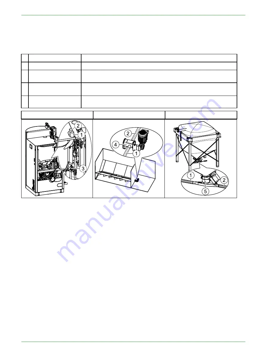
8.2 Pellet suction system

The pellet suction system consists of the pellet hose, air hose and a suction turbine. The suction vacuum turbi-
ne in the hopper conveys pellets in the pellet line from the storage room or fabric tank to the hopper.

Key components of pellet suction system

1

Pellet- Suction hose

Line from the storage room auger or fabric tank to the hopper.

2

Pellet- Return air hose

Line from the suction fan to the storage room auger or fabric tank.

3

Suction fan / Vac
turbine

Located beside the hopper behind the Pellet boiler burner housing.

4

T-piece at end of stora-
ge system auger

Located at front end of the storage room auger, outside the storage
room.

5

Suction Metering
Switch

Located underneath the fabric tank.

Pellet boiler

Version A pellet storage room

Version B fabric tank

8.2.1 Assembly of the vacuum system

The pellet hose and the air hose are flexible spiral hoses made out of plastic. A copper braid embedded in the
hose dissapates static charge when properly grounded.

Assembly guidelines

Bending radius:

The hose should be as short as possible and with as few curves as possible. Bending radius

may never be smaller than 12 inches.

Vertical Lift:

Max difference in height = 10 feet. A difference in height of up to 10 feet can be overcome at

one time.
Larger differences in height must by interrupted with a minimum 4 foot flat section of hose for the pellets.

Impact protection / Velocity Control:

The spiral hose can be run no more than 13 feet in a straight line.

Small bends particularly in front of curves reduces the abrasion of the spiral hose by controlling pellet
velocity.

Installation in the soil and openings:

When burying hose in the ground, it must be inside a protective pipe

such as electrical conduit that is 4 inch in diameter. This pipe must be sealed and may not make any arc mo-
re than 15°.

Hose to be Air Tight:

For trouble free operation, the vacuum system must be 100% air tight at all

connections!
All connection points must be secured with a hose clamp.

Grounding:

The hoses are provided with a copper braid which helps the hose dissipate static charge. In or-

der to ensure this function, copper braid must be connected to a known ground point at each end.

PE 608 USA_FA 2.1

22

Pellet suction system

Summary of Contents for PELLEMATIC SmartXS

Page 1: ...o installing and servicing SAVE THESE INSTRUCTIONS Operating Manual Pellet heating with auger delivery or vacuum suction system for the end user PELLEMATIC SmartXS FA V2 09 Pelletronic TOUCH USA PE 60...

Page 2: ...A_FA 2 1 Version valid from 07 2018 Approved Wohlinger Christian Author Manufacturer MAINE ENERGY SYSTEMS LLC 8 Airport Road P O Box 547 Bethel Maine 04217 E Mail info maineenergysystems com MAINE ENE...

Page 3: ...8 1 Function description 20 8 2 Pellet suction system 22 8 2 1 Assembly of the vacuum system 22 8 3 Storage systems 25 8 3 1 Pellet storage room 25 8 3 2 Flexilo fabric tank 25 9 Operating the Pellema...

Page 4: ...ral 58 20 1 Chimney 59 20 2 Favorite 59 20 3 Local Settings 60 20 4 Malfunction 61 20 5 Information 61 20 6 ModBUS 62 20 7 E Mail 63 20 8 IP Config 64 21 Software 67 22 Maintenance and servicing 68 22...

Page 5: ...afe place for future reference Installation and first startup must be carried out by a qualified installer certified by Maine Energy Systems The installation must comply with the requirements of the A...

Page 6: ...g systems and hot water supply for buildings It is not permissible to use the pellet boiler for any other purpose Reasonable foreseeable inadvertent uses for the pellet boiler are not known The boiler...

Page 7: ...dures to be followed The boiler correctly starts itself when required by building load There are no user adjustments required for the air controls on your Smart XS It is important to have your Smart X...

Page 8: ...ppliance and chimney connector joints an uncontrollable burn or excessive temperature indicates excessive draft The efficiency of your Smart XS in condensing mode running at full power is 96 This is t...

Page 9: ...d lead to death or life threatning injury Warning indicates a situation that could lead life threatning or serious injury Caution indicates a situation that could lead to injury Note indicates a situa...

Page 10: ...enings in the combustion air inlet must never be partially or completely closed Ventilation systems central vacuum cleaning systems extractor fans air conditioning systems flue gas blowers dryers fuel...

Page 11: ...stion R Ri is sk k o of f c cu ut t i in nj ju ur ri ie es s d du ue e t to o s sh ha ar rp p e ed dg ge es s Use gloves for performing all work on the boiler D Da am ma ag ge e t to o p pr ro op pe e...

Page 12: ...ance with the manufacturer s installation specifications or if lacking manufacturers specifications the appliance in question is installed in a manner commonly recognized as safe and correct for the a...

Page 13: ...le e e es sc ca ap pe e o of f f fl lu ue e g ga as s Do not connect this unit to a chimney flue serving an other appliance unless multiple appliances into a single flue is authorized by all authorit...

Page 14: ...g upon the boiler room air as supplied by the air inlet and outlet openings for ventilation in the installation room b Independently of the room air via a separate air intake line with a direct connec...

Page 15: ...and sealed to prevent the escape of condensation Installation without barometric control draft controller is advised Chimney diameter 5 inch And in accordance with chim ney calculation method EN 1338...

Page 16: ...s clogging of the waste water pipe Dismantle all the parts of the waste water line clean and assemble again Information to help interpret the above information Temperature Class T400 are rated for 500...

Page 17: ...of the boiler with no valves between the relief valve and boiler Low Water Detection The Low Water Detection device is connected to the Emergency Stop of the boiler Should a low water condition be det...

Page 18: ...per EN ISO 17225 2 class A1 Ash content max 0 7 Length max 40 mm Diameter 6 mm Fine material max 1 Contents 100 natural wood T Th he e h he ea at ti in ng g s sy ys st te em m i is s s su ui it ta ab...

Page 19: ...pellet storage rooms and warning signs 4 Legislation in your country must be observed regarding building specifications for storage rooms 5 koFEN also offers FleXILO fabric tanks for storing pellets 7...

Page 20: ...controlled by means of the flue gas fan After rising up in the flame tube the combustion gases are passed down through the heat exchanger and via the flue gastube and the chimney into the atmosphere T...

Page 21: ...ine 13 Ash bin 2 Supply and Return 8 Delivery auger 14 Drain valve 3 Air hose 9 Flame return gate 15 Optional Solar Coil 4 Pellet hose suction system 10 Burner 16 Cleaning system 5 Heat insulation 11...

Page 22: ...ending radius The hose should be as short as possible and with as few curves as possible Bending radius may never be smaller than 12 inches Vertical Lift Max difference in height 10 feet A difference...

Page 23: ...ease make sure that you cross the hoses as few times as possible Length of the pellet hose The maximum length for pellets hose and air hose are each 66 feet Assembly Use securing clips and carrying bo...

Page 24: ...Connection of the pellet and air hose to the suction turbine PE 608 USA_FA 2 1 24 Assembly of the vacuum system...

Page 25: ...he customer Information and important notes on setting up storage rooms can be found in the MESys plan ning documents and at www oekofen com Information on installing the auger extraction system is in...

Page 26: ...r 9 1 Description of the control panel The control panel is located in the boiler front cover 1 2 3 1 User control unit Operates the boiler controller and the heating controller 2 Main switch Switches...

Page 27: ...language date and time at Pelletronic Touch 27 9 2 Setting language date and time at Pelletronic Touch Setting the language The factory setting for the language is German Operating Manual PELLEMATIC...

Page 28: ...Setting the date Setting the time PE 608 USA_FA 2 1 28 Setting language date and time at Pelletronic Touch...

Page 29: ...there is a malfunction the correspon ding fault message is displayed at this point instead of the weather icon 6 Favorite 1 adjustable 7 Favorite 2 adjustable 8 Favorite 3 adjustable 10 2 User control...

Page 30: ...new value was not accepted The original value is f Help function inactive g Confirm h Numeric keyboard used to enter values within the min max range 3 Time and date block a Adjustable time or date b...

Page 31: ...and their function 31 Note Although a scroll down menu is open the navigation icons menu items and parameters behind are active and by touching them it takes you directly there Operating Manual PELLE...

Page 32: ...10 3 Main Menu In the Main menu you see all submenus By finger pressure on an icon you reach the respective submenu PE 608 USA_FA 2 1 32 Main Menu...

Page 33: ...Main Menu 33 Menu navigation of Pelletronic Touch Operating Manual PELLEMATIC SmartXS...

Page 34: ...s Off The adjusted operating mode of the heating circuits and DHW is inactive The frost protection function is active Auto The adjusted operating mode of the heating circuits and DHW is active The fro...

Page 35: ...uring Values is in the Main menu Pellematic Heating circuit Domestic hot water Solar Accumulator Return pump Heating Plant In the menu item Allocation you see which heating circuits are allocated to t...

Page 36: ...larger nearby place Search with the following details Postal code location country Postal code country Location country Afterwoods weather data for the next 3 days are downloaded An icon for the curre...

Page 37: ...weather data for the next 3 days are downloaded An icon for the current weather is displayed on the opening window Note This feature requires an internet connection Cur temperature Current temperature...

Page 38: ...eating times according to the Set room temperature Heating The Furnace heats constantly according to the Set room temperature Set back The Furnace heats constantly according to the Set back room tempe...

Page 39: ...uring values Actual value Set value Inputs sensores Outputs pumps mixer and motors Outside Temperature actual Outside Temperature Boiler Temp actual Boiler Temperature Booster Status Booster On Off Fl...

Page 40: ...for these hea ting days Mo Th 8 With and you switch between the heating blocks You can deactivate heating days in the heating block and activate in another 4 The heating times for Mo Th are assig ned...

Page 41: ...en the party function deactivates itself automatically 15 4 Vacation The holiday programme cancels the heating times and heats for the entered period on the set temperature level Vacation is in the Ma...

Page 42: ...the associa ted flow temperature for a heating circuit Base point adjustable from 68 113 F With the change the of base point you provide a parallel shift of the heating curve H limit heating If the av...

Page 43: ...time to reach the adjusted roomtemp heating Room thermostat influence If the measured room temperature deviates from the set room temperature the heating controller corrects the flow temperature with...

Page 44: ...ts the cycling On Off On Off of the heating circuit pump If the Set room temperature room temperature hysteresis is reached the associated pump stops If the Set room temperature is 1 C the pump switch...

Page 45: ...n the time programme to the desired hot water temperature Outside the time programme the installation heats to Watertemp min On The system heats up the domestic hot water continuously on the Water tem...

Page 46: ...he accumulator temperature is above the switch on temperature during the set heating times the heating circuit is heated until the switch off temperature is reached Solar pump Heating program only act...

Page 47: ...1 Measuring values Domestic hot water Measuring values DHW is in the Main menu You see all the Heating circuit corresponding measuring values Actual value Set value Inputs sensores Outputs pumps mixe...

Page 48: ...Off DHW Return pump inactive Auto Temperature regulation within the time programme If the return temperature sensor of the DHW Return pump reaches the Switch off temperature the pump switches off If t...

Page 49: ...is in menu DHW Return pump You see all the Heating circuit corresponding measuring values Actual value Set value Inputs sensores Outputs pumps mixer und motors 17 2 Time programme DHW return pump In t...

Page 50: ...s Solar is in the Main menu Solar has following menu items Measuring values Solar Solar circuit 1 2 Solar energy yield 18 1 Measuring values Solar Measuring values Solar is in the menu Solar It displa...

Page 51: ...for solar cooling If the temperature in the ACC is higher than the ACC temp Max the solar pump switches off The limit sensor measures the temperature in the ACC The solar circuit pump is switched off...

Page 52: ...Energy is in the menu Solar Yield measuring of solar energy has following menu items Actual Display of the current solar energy refreshes every 60 sec Yield Day Display of todays solar energy since 0...

Page 53: ...atic has following items Operating Mode Measuring values Pellematic Permanent operation Locktime Continous run Full power Suctionprobe Filling level Suction turbine 19 1 Measuring values Measuring val...

Page 54: ...orks the same way like the heating circuit time programme 19 3 Continuous running Continuous running is in the menu Smart XS The burner motor runs in permanent operation and transports pellets to the...

Page 55: ...burner auger run time is calculated automa tically by the PLC depending on the rated power and the boiler setpoint temperature The burner motor is controlled accordingly You can reduce or increase th...

Page 56: ...when filling level rerises above the adjusted Minimum weight Note Only displaed if mode is set on Textile tank 19 7 Suction turbine Suction turbine is in the menu Smart XS Set a Time full hours at whi...

Page 57: ...Cleaning 57 19 8 Cleaning Cleaning is in the menu Smart XS Here you activate the function Cleaning On Off Duration of boiler cleaning in seconds Operating Manual PELLEMATIC SmartXS...

Page 58: ...ol related settings and individual operating options for the customer General is in the Main menu The menu General includes Chimney Favorit Values Local setting Datalog Malfunction Info Save Load ModB...

Page 59: ...perature and the rest of the time limit After the expiry of the time limit the function chimney ends time of expiry the operation Chimney sweeper ends The button Cancel ends the function Chimney 20 2...

Page 60: ...g menu items Language Unit Date Time Choose between the languages German English UK English U S French Spa nish Italian Dutch Danish and Russian You can choose between isometric and imperialist number...

Page 61: ...y It remains until it is acknowledged The menu remains the fault incident reports as long as they are corrected up 20 5 Information Information is in the menu General In the menu item information are...

Page 62: ...ote The Modbus registers may be set not less than two hours in cyclic operation otherwise the life span of the operating device can decrease Off TCP Server Defaultport for ModBUS is 502 PE 608 USA_FA...

Page 63: ...server Only the recipient address needs to be configured To ensure maximal flexibility E mail settings can set individually Port used for sending email depends on provider Select encryption mode speci...

Page 64: ...equired in the local network GW The gateway enables the touch operating device the access to the internet D1 D2 Server which provide routing information Set DHCP On or Off depending on your network En...

Page 65: ...spe cial services e g 25 Mail 80 Web and so on The ping prevents the internet connection from beeing closed by the router Therefore a query to the Maine Energy Systems server is started at certain tim...

Page 66: ...be used But the remote controll of the Touch operating device remains active and can be uses as before via port forwarding DynDns fixed external IP LAN and so on All functions for the network interne...

Page 67: ...Software 67 21 Software Software is in the Main menu Software shows you the name of the current software Operating Manual PELLEMATIC SmartXS...

Page 68: ...in a manner inconsistent with operating instructions in the manual Ashes should be placed in a metal container with a tight fitting lid The closed container of ashes should be placed on a noncombusti...

Page 69: ...ge Ashbox 22 2 Cleaning the boiler every year The pellet boiler is equipped with an automatic cleaning system that cleans the heat exchanger every day In ad dition you need to clean the boiler manuall...

Page 70: ...witch off the main switch before starting any mainte nance work on the system R Ri is sk k o of f c cu ut t i in nj ju ur ri ie es s d du ue e t to o s sh ha ar rp p e ed dg ge es s Use gloves D Da am...

Page 71: ...Cleaning the boiler every year 71 Emptying of the ash box also possible during operation Note Acknowledge the error message Ashbox Operating Manual PELLEMATIC SmartXS...

Page 72: ...Cleaning the boiler the boiler must be switched off before Cleaning the heat exchanger PE 608 USA_FA 2 1 72 Cleaning the boiler every year...

Page 73: ...Cleaning the boiler every year 73 Cleaning the waste water pipe the boiler must be switched off before Operating Manual PELLEMATIC SmartXS...

Page 74: ...enance intervals We recommend taking out a maintenance contract with your service technician 22 4 Repairs Only authorised specialists may carry out repair work on this system Use original spare parts...

Page 75: ...ure that no flammable materials are stored in the boiler room Make sure that no washing is hanging in the boiler room Check the display on the control panel for malfunction messages Check the flue gas...

Page 76: ...f the heating system before entering Check the level of pellets in the textile tank and order more pellets in good time 22 6 Disposal information Ensure environmentally sound disposal in accordance wi...

Page 77: ...Pellet boiler cautionary markings 77 23 Pellet boiler cautionary markings Operating Manual PELLEMATIC SmartXS...

Page 78: ...PE 608 USA_FA 2 1 78 Pellet boiler cautionary markings...

Page 79: ...Pellet boiler cautionary markings 79 Operating Manual PELLEMATIC SmartXS...

Page 80: ...e or replace it with the most comparable model available from MESys at the time of the replacement The foregoing timelines begin to run upon the date of initial operation and shall not be stalled toll...

Page 81: ...ETS OUT YOUR EXCLUSIVE REMEDIES WITH RESPECT TO PRODUCT WHETHER THE CLAIM ARISES IN CONTRACT OR TORT INCLUDING STRICT LIABILITY OR NEGLIGENCE OR OTHERWISE THIS WARRANTY IS IN LIEU OF ALL OTHER WARRANT...

Page 82: ...uthor Manufacturer MAINE ENERGY SYSTEMS LLC 8 Airport Road P O Box 547 Bethel Maine 04217 E Mail info maineenergysystems com MAINE ENERGY SYSTEMS LLC www maineenergysystems com Subject to modifcations...

Reviews: